In the housing I have taken into account the installation of a powerbank battery.
These batteries are available everywhere around 10euro (Action). When purchasing a powerbank, make sure that the battery is as flat as possible.
There are power banks that do not use flat cells, but round cells.
These take up a lot of space, and a flat battery is easier to attach with a piece of double-sided tape.
In many projects where a power bank was used, I saw that the USB charging connector of the power bank was brought out.
Personally, I found this a bit redundant, because we have already released 2 (3) USB connectors from the STM board, I found a 4th one not really great.
It would be nice if I could use the USB connector that is also used for programming (ST-LINK) of the board, and for the PC connection (Antscope).
This is USB Connector CN14.
In order to do that, I had to make a small adjustment on the board.
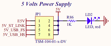
The 5V of the USB Connector CN14 (5V_USB_ST_LINK) is led via IC U8 to an 8-pole header JP1 with the name 5V_ST_LINK.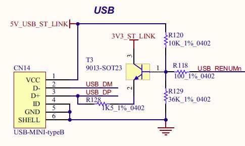
Through this header it is possible to choose where the 5V power source should come from.
By default it is set to 5V_ST_LINK Pin 3 and 4, coming from U8
Below you can see where the voltage of CN14 comes in (5V_USB_ST_LINK), and continues via the IC U8 to JP1 as 5V_ST_LINK.
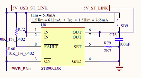
Since this IC can process a maximum of only 1.2A, it is not possible to connect the charging input of the power bank to header JP1 pin 3 (5V_ST_LINK) via this IC.
The power bank will pull more than 1.2A during a firm load.
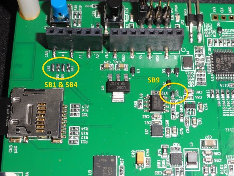
Now it has been taken into account to bypass the IC, one can do this by soldering jumper SB9. A solder blob is sufficient.
Now that we have done this we can connect the 5V charging input of the power bank to pin 3 of JP1. As soon as the USB is connected to an external adapter, the powerbank will be charged.
The PC function is now also available, when connecting to the PC you can also program and / or use external software such as Antscope.
Feeding the STM board also requires the necessary attention.
Where we removed the JP1 jumper (Pin 3 and 4) we can not just connect the output of the power bank to pin 2,4,6 or 8.
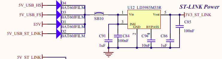
Due to the lack of jumper U12 is no longer fed.
If there is no voltage on the output of this IC, the board comes into a sort of “RESET” loop, the screen will then stay white and not restart.
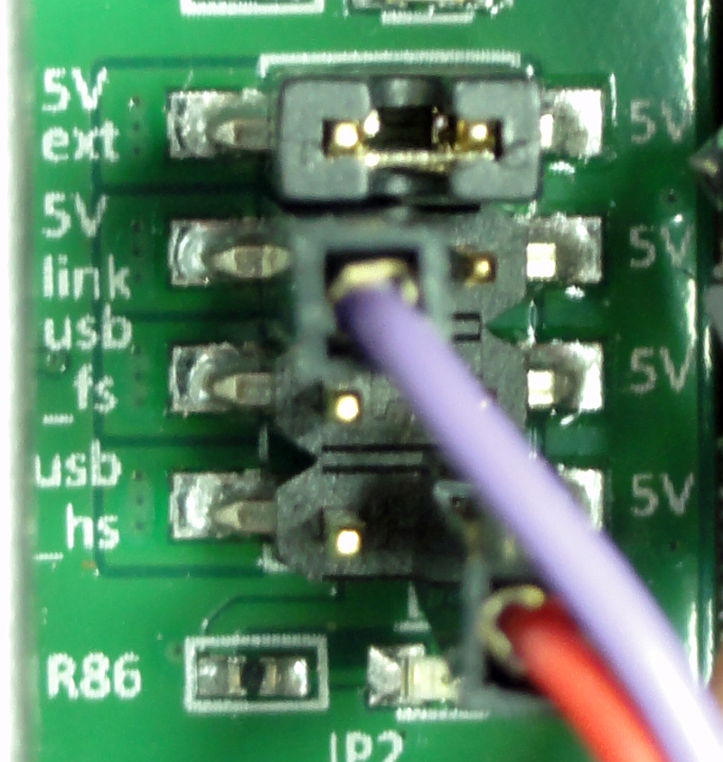
To fix this, we place the jumper back on JP1 but then pin 1 and 2.
In this way the 5V supply voltage is fed back to U12 via E5V (5V ext), and the board will start again. Why E5V (5V ext)?
If the jumper is connected to pins 5 and 6 or 7 and 8, this also works. But if one then connects the PC to USB connector CN12 and / or CN13, the STM board is also powered.
So fed twice. And that is not the intention.
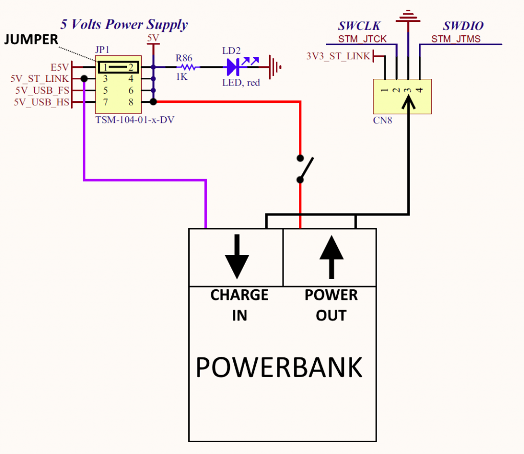
A total picture of how the power bank should be connected.