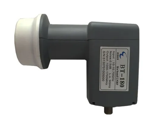
Recently I got my hands on a very good performing LNB for 10 ghz amateur television.
Available on aliexpress under the name BT-180 with an LO of 9GHz.
There was only a slight problem using it at my location.
Here in the Netherlands there are 2 unofficial frequencies for ATV on 23cm. 1252 and 1280MHz.
And with 1252 we just have a problem here.
The repeater here near me PI6HLM is at 10.250GHz
Simple math: 10250MHz- 9000Mhz(LNB LO) = 1250mhz IF.
So the problem is, if you start transmitting locally on 1252, the IF on your receiver is surpressed by your own transmitter on 23cm.
To prevent this, the LO must be tuned to a frequency so that the IF frequency is far away from your own transmitter frequency.
Also Note, Adjusting to an LO of 8900Mhz same issue when the received station is on 10.150GHz.
So this is no option either. Adjusting the LO to 8950 or 9050 will be fine, but harder to calculate with 🙂
Fortunately with these LNBs this is very easy to adjust.
This LNB uses a DRO. above this DRO is a tuning screw, which only needs to be turned to tune the LO frequency up or down.
You can adjust the LO in several ways:
1.
On the gamble, keep turning the screw until you have an signal at the desired IF frequency.
This is a possibility but it takes a lot of time. and very difficult to precisely tune the LO to frequency.
But the advantage is that you do not need any extra measuring instruments.
2.
Measure the LO frequency, then adjust to the new LO frequency. with a Spectrum analyzer and/or frequency counter.
This is the fastest method, but since not everyone owns a spectrum analyzer or frequency counter for +/- 10GHz, this is one of the few options.
3.
My used instruments consist of using a NanoVna or LiteVna or SV4401A as a signal generator, and a TinySa(ultra) as a spectrum analyzer.
Signal generator? “It can’t transmit at 10GHz at all, can it?”
Yes and No,
We use harmonics from the signal generator!
In fact you can use any Signal Generator to create harmonics, but remember the more harmonics needed the weaker the signal is at the desired harmonic frequency.
Suppose we want to generate a signal of 10250mhz.
Then we can use the following harmonics:
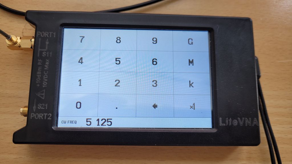
10250MHz / 2 = 5125MHz (Possible with the LiteVNA 6.4)
10250MHz / 4 = 2562.5MHz (Possible with the LiteVNA 6.4)
10250MHz / 8 = 1281.25MHz (Possible with the LiteVNA 6.4)
10250MHz / 16 = 640.625MHz (Possible with the LiteVNA 6.4 and NanoVNA!)
I myself will use the TinySA Ultra and the LiteVNA 6.4 to readjust the LNB.
What is also important with this LNB is that it only works on 18V!, so not on 13V! so pay attention to that!
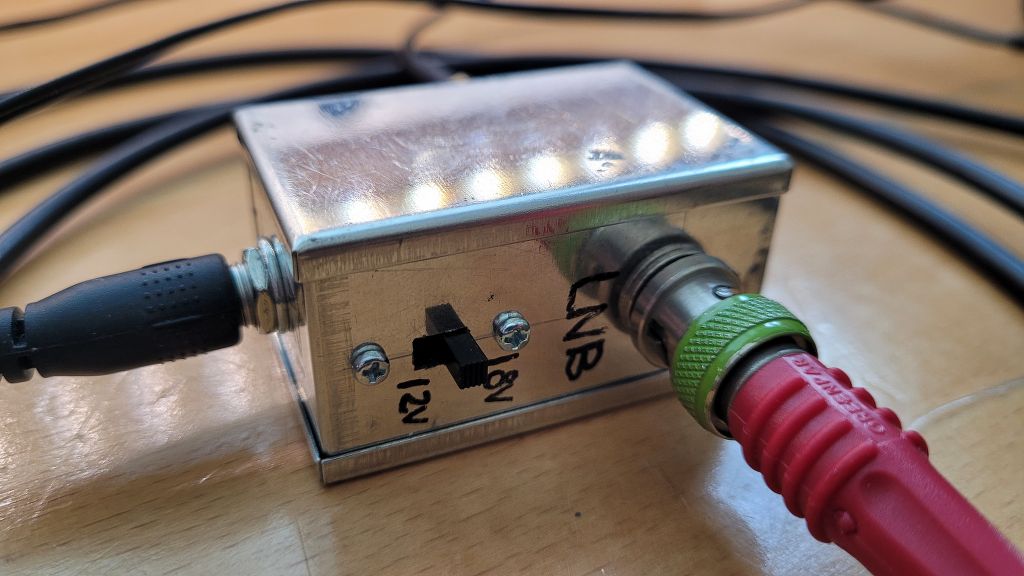
I made a simple tool with a DC/DC upconverter. which I feed with 12V and with a switch I can then choose between 12 and 18V to feed the LNB, together in 1 housing with a Bias-Tee.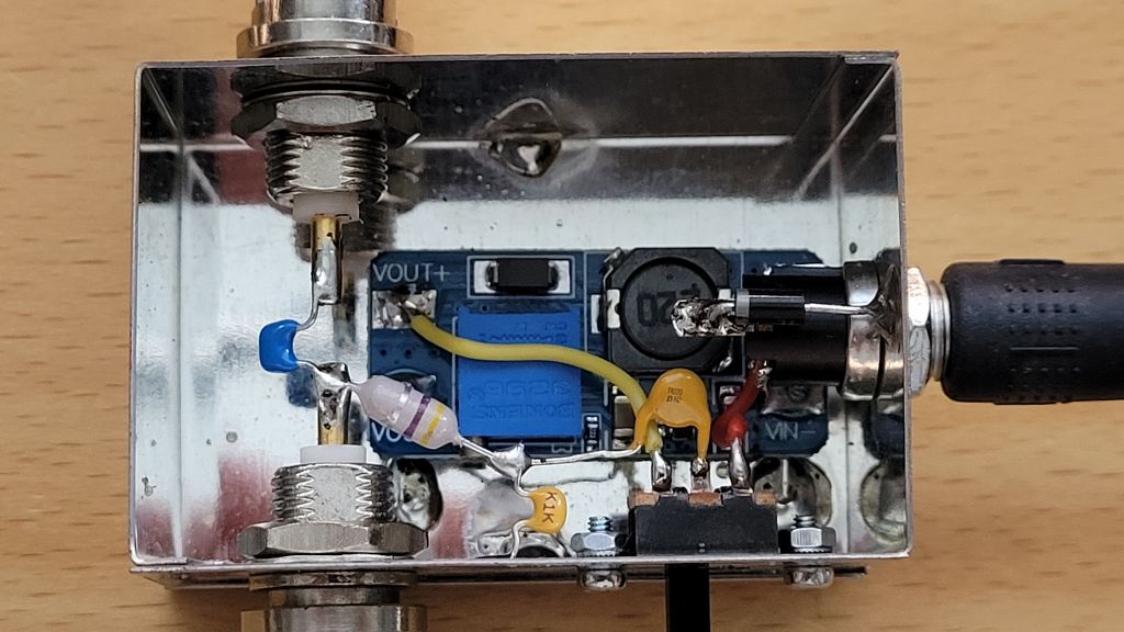
Operational Setup, In my case this LNB was set temporarely to 9050MHz for testing.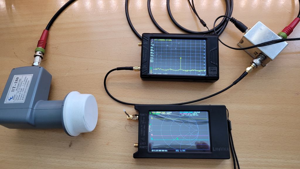
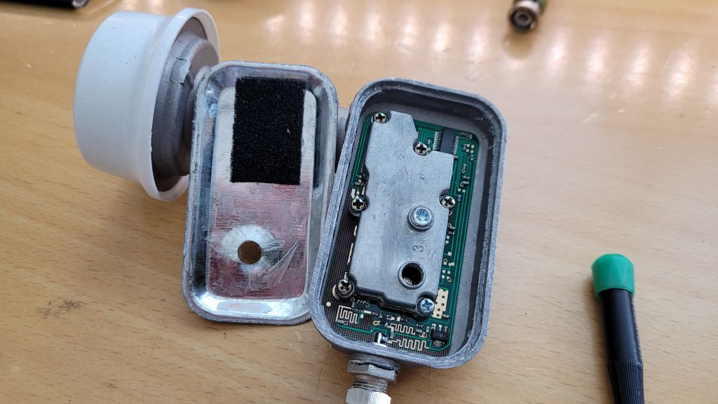
Opening the LNB in the correct way without breaking any internal plastic clips. Open in the following way.
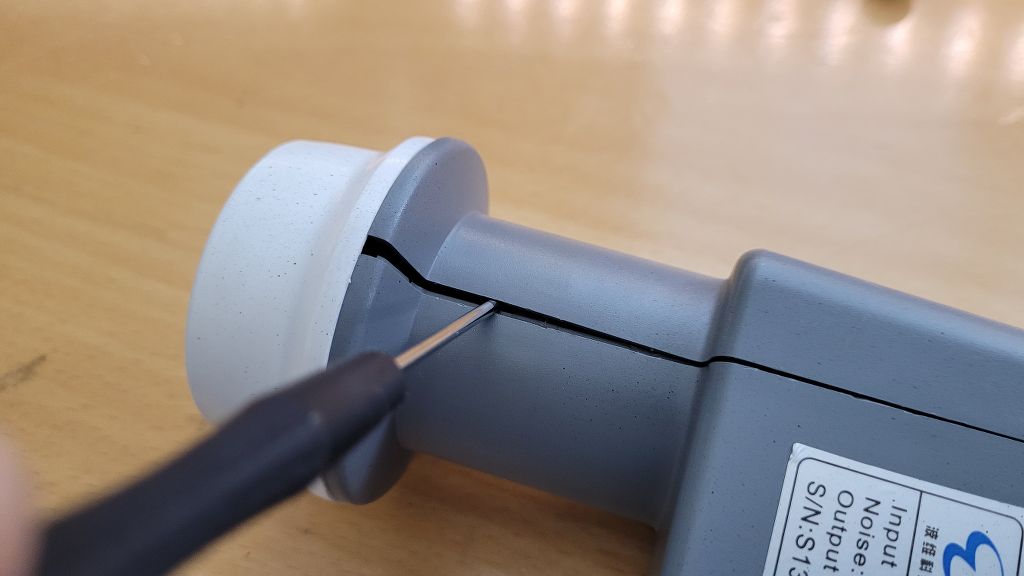
 After this you can take off the top cover easily and take out the lnb unit.
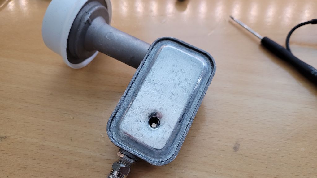
The LNB in all its glory!.
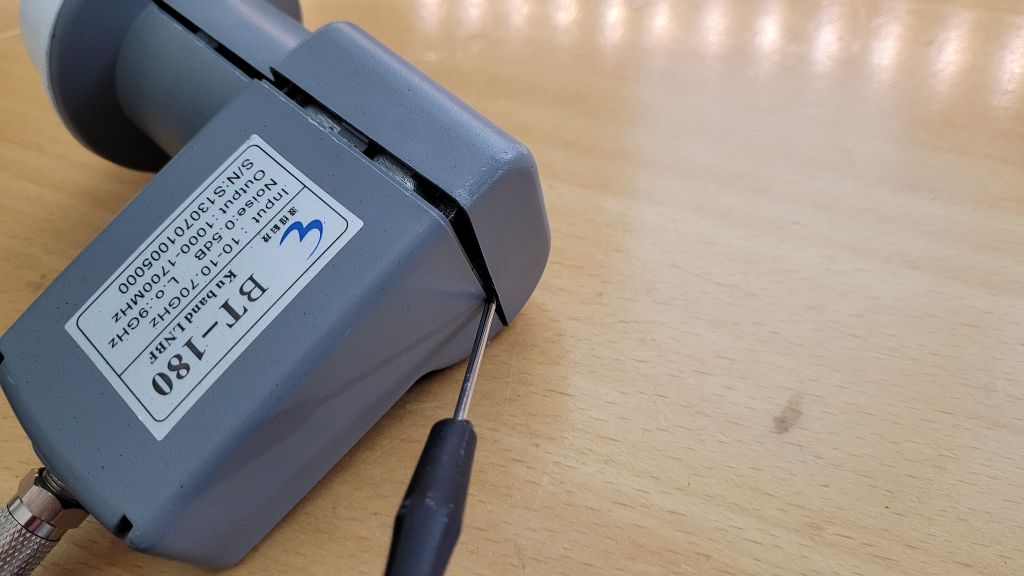
First you have to remove the sealant arround the cover to be able to take to cover off.
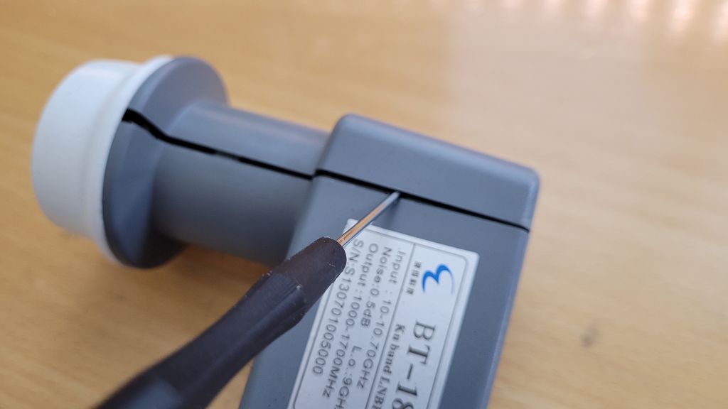
If you look closely you will see there is no screw here. this is for most BT-180 thats we have received. some have screws here also, but they are not functional.
This because the whole vertical polarisation is not present SMD like wise.
Therefore only Horizontal is active, and as we know.. Horizontal in Sat world = 18V 😉
Here when opened you can clearly see the second (horizontal) LO adjustment screw.
Ok lets get started adjusting the LO.
In my case the LO was set to 9050MHz for testing purpose.
But now I want it to change to 9100MHz.
First thing we do is setup the signal generator, to obtain a signal at 10250MHz I will use the second harmonic of 5125MHz.
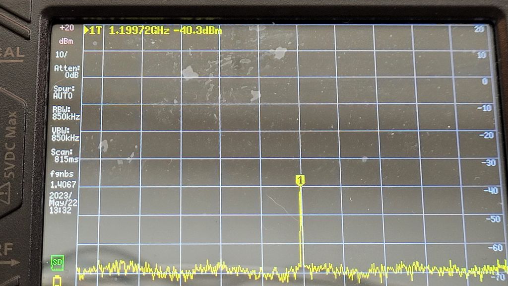
Then we setup the TinySA(ultra) in my case, to have a spectrum view from 1100 to 1300MHz, and power up the LNB.
As expected we should now see a signal apear at 1200MHz
10250 – 9050 = 1200MHz
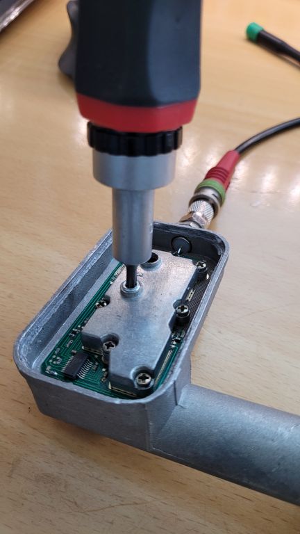
Now we Adjust the screw on the LNB.
The principal is.. the distance between the screw and the DRO will cause the LO resonate at a specific frequency. the closer the screw to the DRO will result in a higher LO frequency, and the wider the frequency will lower.
!!! NOTE !!!
Be careful not to hit the DRO when screwing in! it can be irreparably damaged!
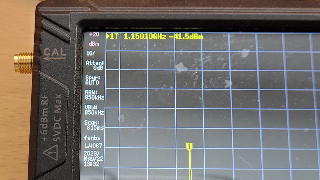
In my situation, the screw must be screwed in a bit (Clockwise) to increase the LO frequency by 50MHz to obtain a LO of 9100MHz / IF 1150MHz output.
The screw used is a Torx T15.
After some re-adjusting the screw, I obtained a reasonable IF output frequency at 1150MHz!
Everything ready now!
The cover can be put back on, it can be sealed with an acid-free sealant.
Place back in the housing and dish, and you are ready to go!