STL FILES: downloads here
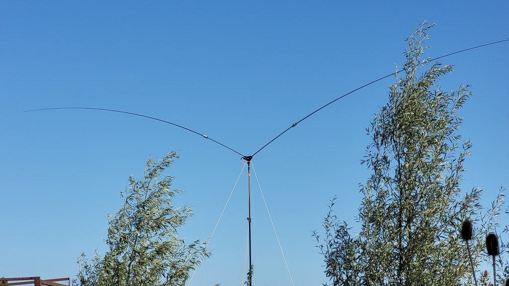
Although the design of the V Dipole is not new at all, the past few months after building the V Dipole have proven to be a great success.
Success in the sense of being very quick to set up, requiring a small footprint for guy wires, and still being able to set up a full-size dipole.
This has piqued the interest of many people.
I’ve now managed to neatly store everything in one bag: the mast, a tube with various telescopic antennas, guy pins, and guy wires.
A few weeks ago, I suddenly thought, if I could also incorporate 40m into this antenna, that would be great. And it saves me from having to carry a extra bag of masts/wires.
The idea arose to make a shortened dipole for 40m, but still using the 5.5m telescopic antennas.
I also considered it important that everything fits together in the bag.
So, the extension couldn’t be longer than 1.2m (the bag is 1.25m).
The length of the extension tube was quickly chosen. The local hardware store sells 16mm x 1mm x 1000mm aluminum tubes.
Same tube used for mounting the body on the Tripod Mast.
This is, of course, not an ideal length for making a shortened dipole, but hey, it’s all about simplicity, quick on-site assembly, and still being able to achieve a decent result.
Meanwhile, I also came across the VK3CPU website.
https://miguelvaca.github.io/vk3cpu/
He has nice graphical calculators for MagneticLoops, Inductors, and Magnetic Inductors.
They also have a very nice tool for making a shortened dipole.
https://miguelvaca.github.io/vk3cpu/short_dipole.html
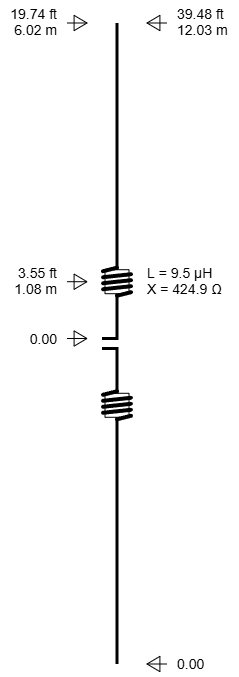
By sliding various parameters, I was able to quickly enter my shortened 40m dipole and calculate the desired inductance for the shortening coil. Note: This is not a trap!
Below you can see how I designed the antenna.
The extension tubes, including coils, are approximately 110cm long. The telescope antenna will be mounted on them.
The total length could be 12.5m, but I kept it at 12.0m to be on the safe side, allowing me to play around with the resonance frequency a bit.
There were several challenges.
- Can the current body handle the torque of the extended antenna? I only had 20mm of space in the body to slide the tube into.
- How do I ensure that the extension tube can be screwed into the body, just like the telescope antenna with its M10 thread? And, importantly, how do I ensure that the M10 thread of the tube makes contact with the tube itself?
- How do I design the extension coils? 3D print for sure, but how?
Step 1: The Body
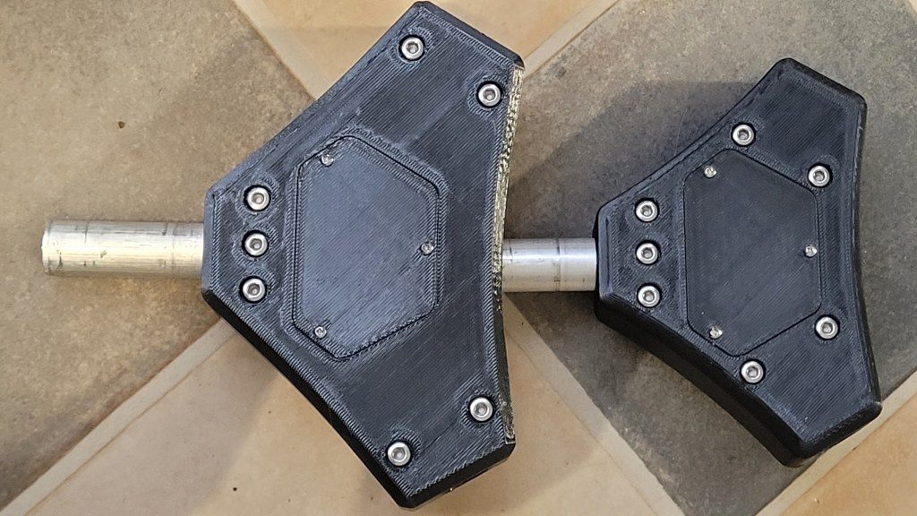
I found the 20mm insertion space too small on the old body.
So I designed a new body that can now accommodate 30mm insertion of tubing.
I also designed the bolts in the body directly next to the tube insertion space to ensure proper strength.
Here you can see the body has increased in size (width), now having 30mm insertion space. (Left new version, Right older version)
Step 2: Electrical Connection of M10 Thread to Tubing
This took me a while. Since I want to make these kinds of projects as much as possible with household materials, except for a 3D printer, I didn’t want to use Machined M10 threaded bushings that I could simply press in.
This project should be accessible to everyone.
Then I decided to create a kind of anchor/barb design.
A piece of M10 threaded rod. 4 sides are grinded down, this is only needed for drilling the holes.,Thinking about it.. 2 flat sides should be enough too.
I drilled crosswise holes through it and made some kind of anchor/barb design with copper wire. I also printed a guide bushing with an M10 internal thread so that the thread is perfectly centered in the tube during pressing.
This is rock solid and now creates a perfect connection with the tube.
Step 3, Coils
In the first test phase, I permanently mounted the extension tube to the extension tube.
Only the telescope antenna had to be screwed into the extension coil.
This immediately introduced limitations.
I could never install a different coil for a different band.
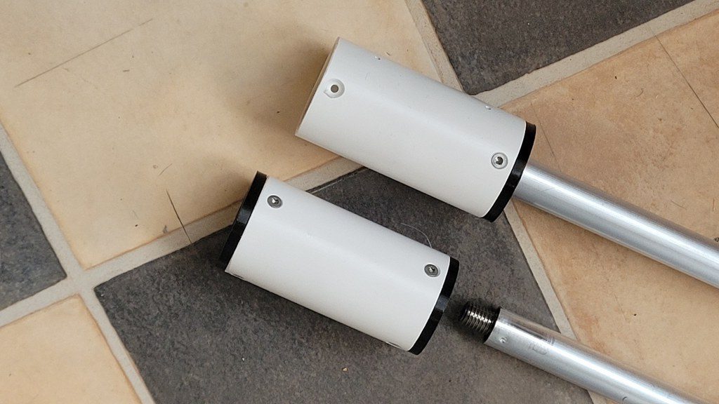
So, in the final design, I added M10 threads to both sides of the extension tube, and the coil now has two internal M10 nuts. Now I can always choose to install a different set of coils for a different band.
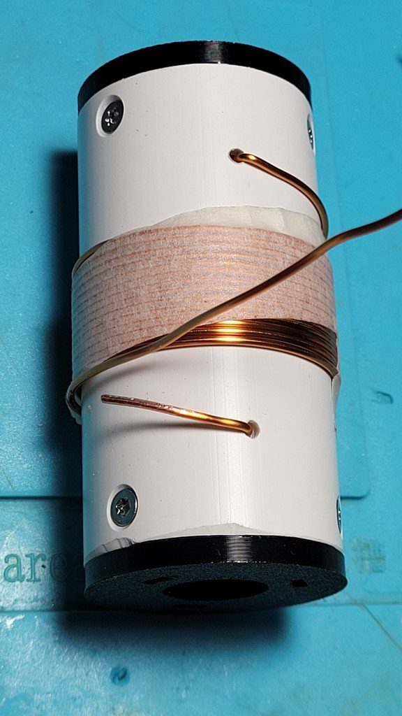
Below you can see the final result for the coil assembly.
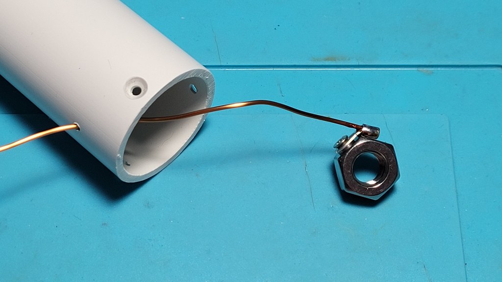
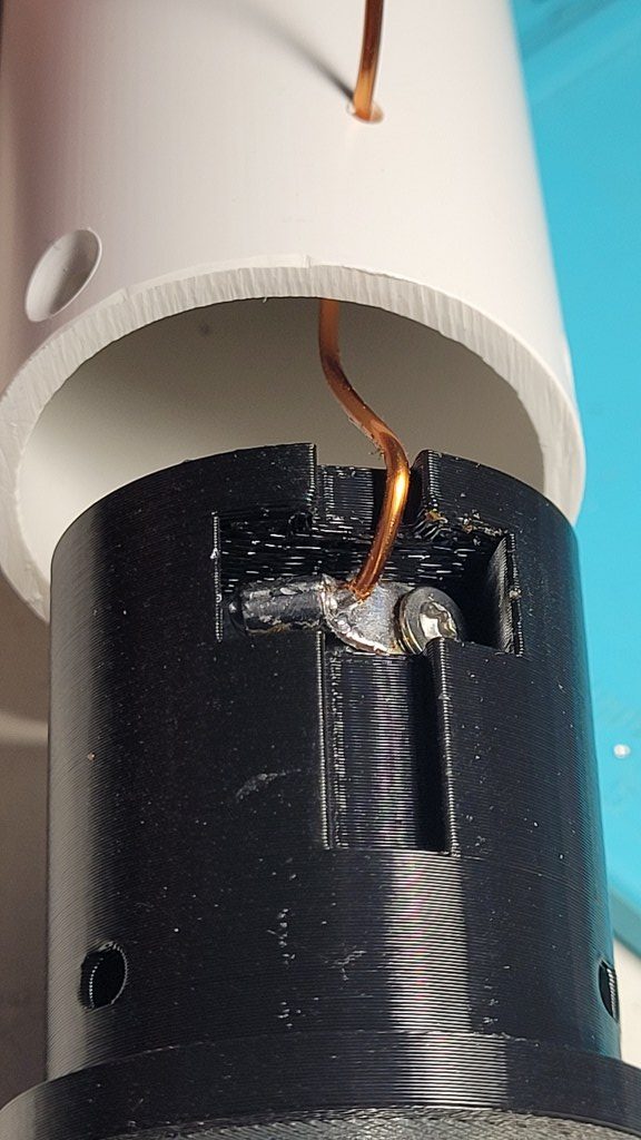
There are two “caps” mounted on both sides of a 40mm PVC plumbing pipe.
This pipe was chosen to absorb the force.
The length of the tube was chosen so that the two end caps fit with a small space of +/- 5mm between them.
The tube length is 80mm.
Printing the coil in one piece would still be too weak.
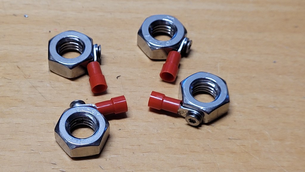
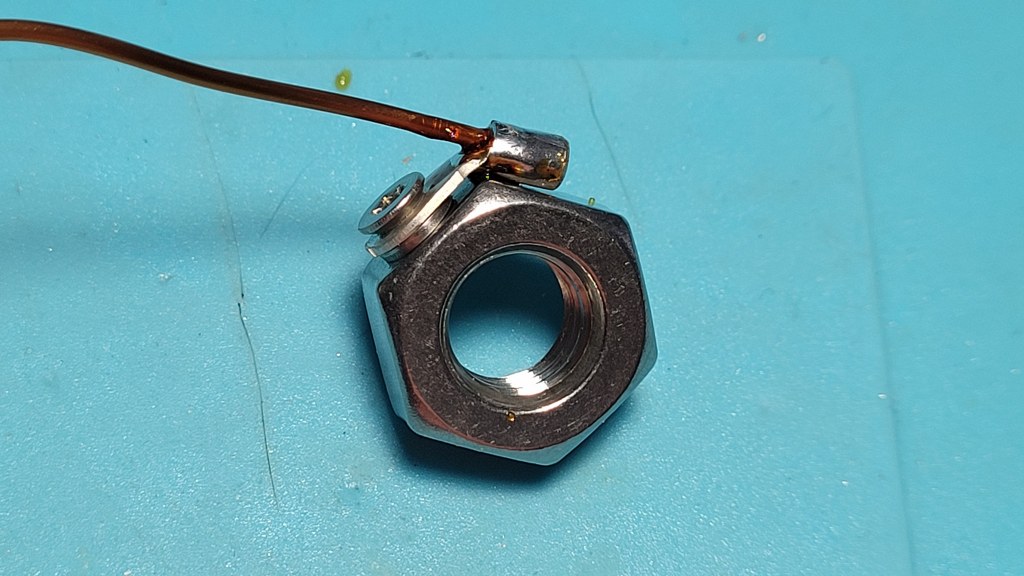
The “caps” contain an M10 nut.
I tapped an M3 thread into this nut. A lug with a piece of copper wire is attached to this lug. This copper wire eventually exits through the PVC pipe, where I can then attach the coil.
The number of turns is a bit experimental.
You can easily use the winding result from the VK3CPU calculator, but bring a few extra turns. Just in case.
You want to achieve maximum extension of the telescope antennas. If you need to retract the telescope a considerable distance, carefully remove one turn from the coil until you reach the desired result.
For convenience, I’ve made an extra set of coils so I can experiment in the field.
When done. just solder the 2 ends togheter.
Here are two prepared coils, wrapped in tape, so the windings can’t move.
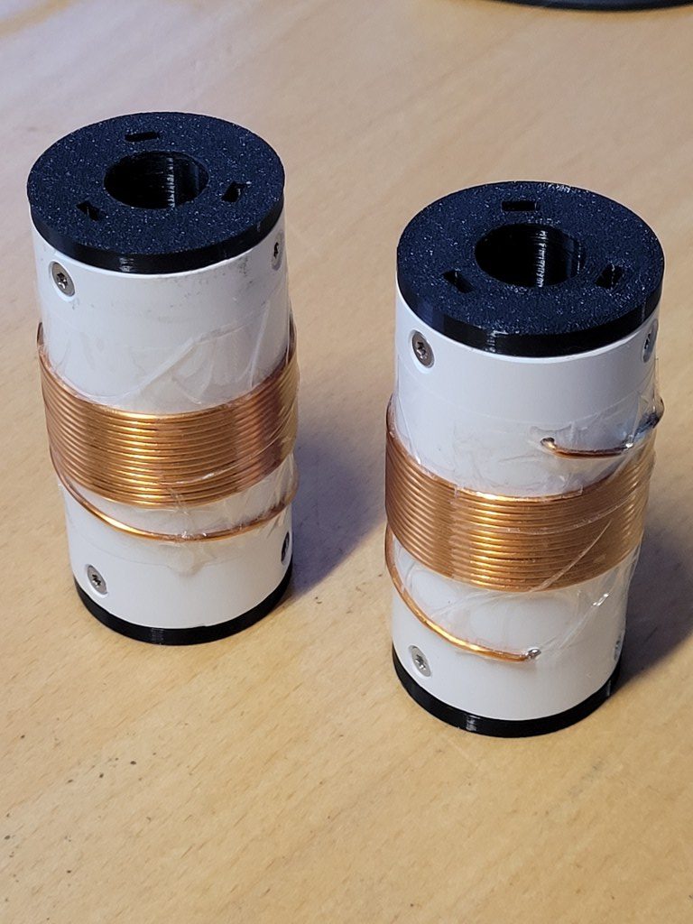
The idea is that you can swap the coils this way for other values/bands.