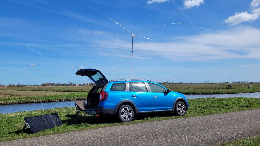
This winter, I certainly didn’t sit still. While many people slow down during the colder months, I actually used the time to focus on experimenting, improving, and building. One of the main projects I’ve been working on is the further development of my portable V-Dipole system, which has been evolving step by step over the past seasons.
 Looking back at last season, I had already extended the original design quite a bit. The most recent additions at that time were the wire dipole expansion and the dedicated 40-meter extension kit. That combination worked very well in practice and gave me solid multi-band capability with a relatively compact and portable setup. It was reliable, easy to deploy, and perfect for portable operation—but as always, there’s that constant urge to improve and innovate.
During the winter, I started thinking about how to push the concept even further. The idea was simple in theory, but more challenging in practice: what if I could expand the system in such a way that multiple bands could be used simultaneously, without constantly switching or reconfiguring the antenna? That led to the development of a completely new variant of the V-Dipole.
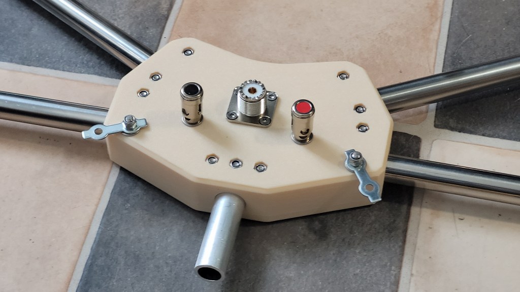
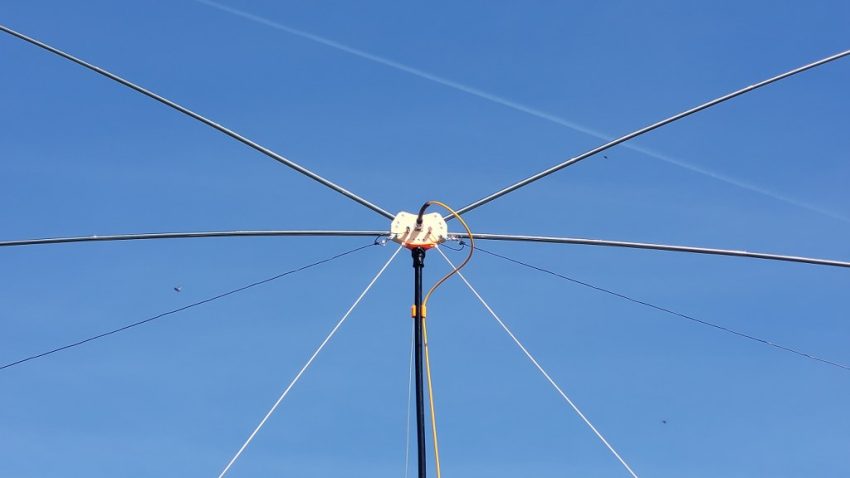
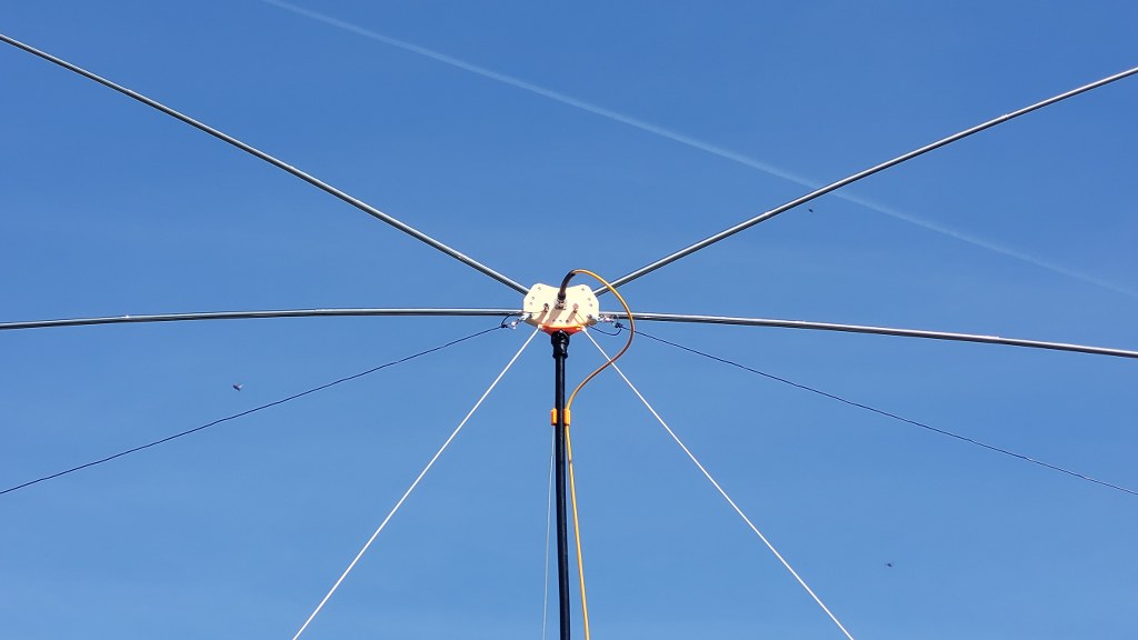
In this new design, I added the possibility to mount two additional telescopic antennas to the existing structure. This effectively transforms the system into a tri-band setup, allowing operation on three different bands at the same time. The concept relies on the idea that each element is tuned for its specific band, and that—due to impedance differences—the elements should theoretically interfere as little as possible with each other.
Of course, as with many RF designs, theory and reality don’t fully match.
Today, I finally had the opportunity to properly test the system in real-world conditions after assembling everything and doing some initial rough tuning. As expected, there was still some interaction between the elements. Even though one band appears as a high impedance on another band (and therefore should be “invisible”), in practice there is always some level of coupling. This resulted in slight detuning effects across the bands.
So it became a matter of careful adjustment—tweaking element lengths, repositioning slightly, and iterating step by step. After some time spent fine-tuning, I managed to achieve a very satisfying result: a properly resonant tri-band configuration.
The final setup is now tuned for:
- 10 meters at 28.500 MHz
- 20 meters at 14.150 MHz
- 40 meters at 7.100 MHz
All three bands show good resonance and acceptable behavior, which makes the system very usable in practice. Achieving this balance between the elements was definitely the most interesting (and challenging) part of the project.
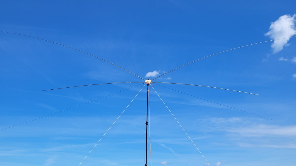
And honestly—besides the technical success—it just looks amazing.
With multiple telescopic elements extending in a V-shaped configuration, the antenna has a very distinctive and somewhat futuristic appearance. It almost looks like something out of a sci-fi setup rather than a typical portable antenna. That alone makes it a fun piece of equipment to bring into the field.
This is still an evolving project, and I’ll continue refining it where possible. But I’m very happy with the current results.
The STL files for the mechanical parts will be made available for download soon, so others can experiment with the design as well.
So… stay tuned!