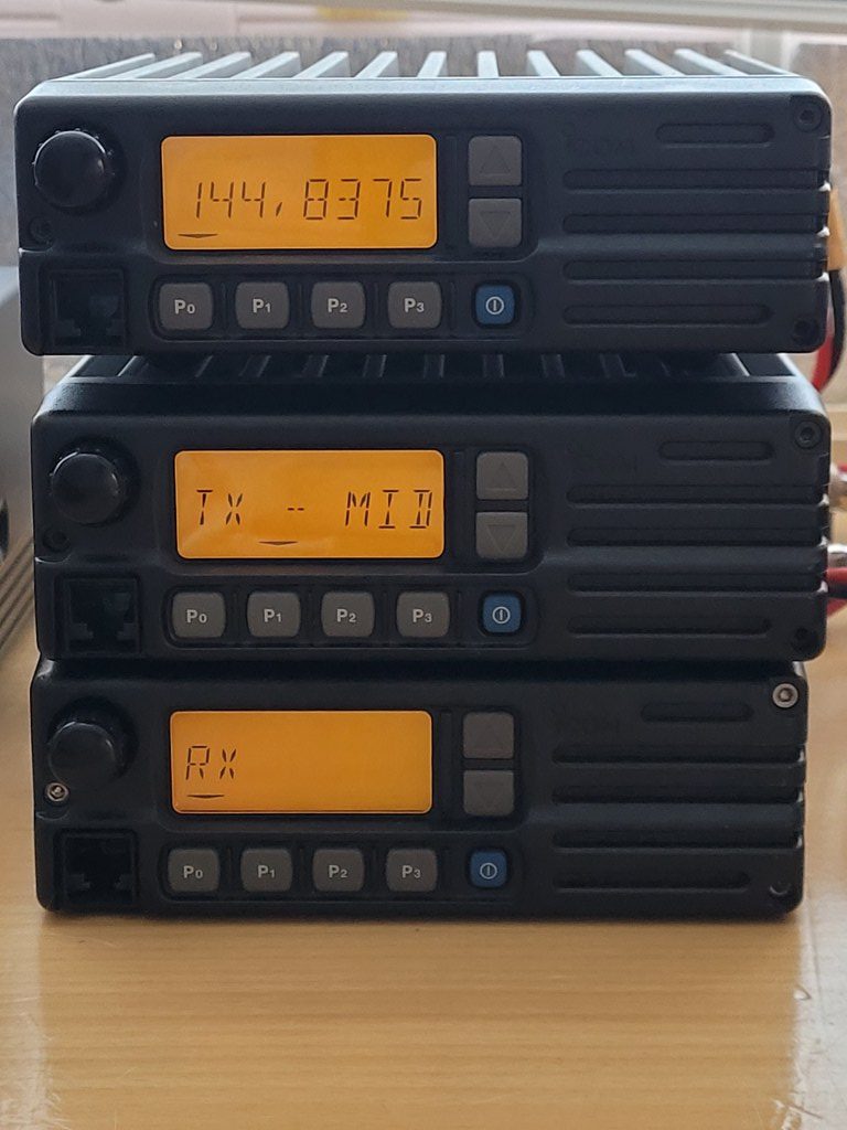
I recently purchased a number of Icom Trunking radios with the intention of using them for digital use. That is, to use them to create a Hotspot / Repeater for D-Star and/or Yaesu Fusion (C4FM).
I had once bought an IC-F1010 to use on VHF for packet radio.
The adjustment for this was simple.
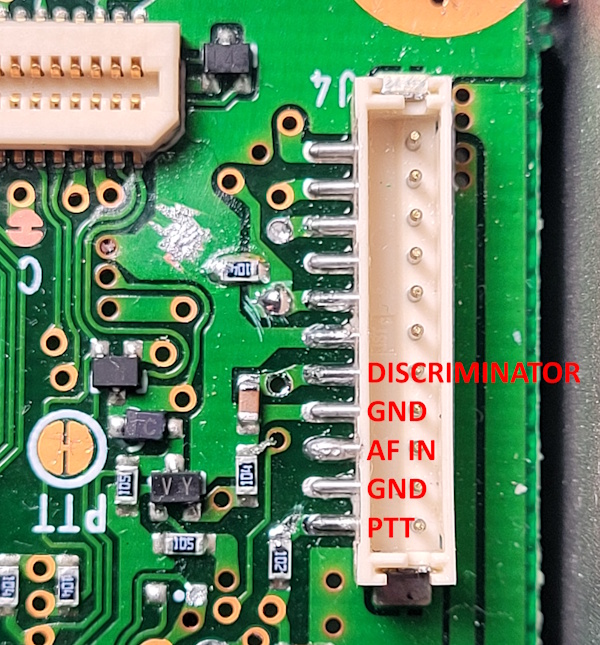
Because these are trunking radios, they have an optional internal connection for a cable (OPC-617) that can then be led outside.
The internal connector of this cable contains all the necessary connections to connect a Packet Modem, such as:
– Mic Input
– Discriminator Output
– PTT
– GND
A Discriminator output is virtually essential for all forms of Data communication. There is no filtering at all directly from the IF. The entire AF frequency range is output linearly.
This connection was sufficient for packet radio.
When I started using this connection with an MMDVM Repeater HAT, I quickly discovered that the signal I was transmitting wasn’t really that great.
Where and where I received the signal the BER (Bit Error Rate) was high between 1 and 5%.
This is still usable/acceptable for Voice operation. But Data like Messages appears corrupt.
Pictures sent via D-Star are also sent poorly or not at all.
After some research I discovered that unlike the discriminator output, the Mic input is filtered. Also called Pre-Emphased.
Here the audio signal is restructured in such a way that it is presented to the VCO in a certain way.
This immediately poses the problem.
Since digitally modulated audio is almost always linear, unlike speech, this filtering actually distorts the modulated audio, and that causes problems when receiving the transmitted signal.
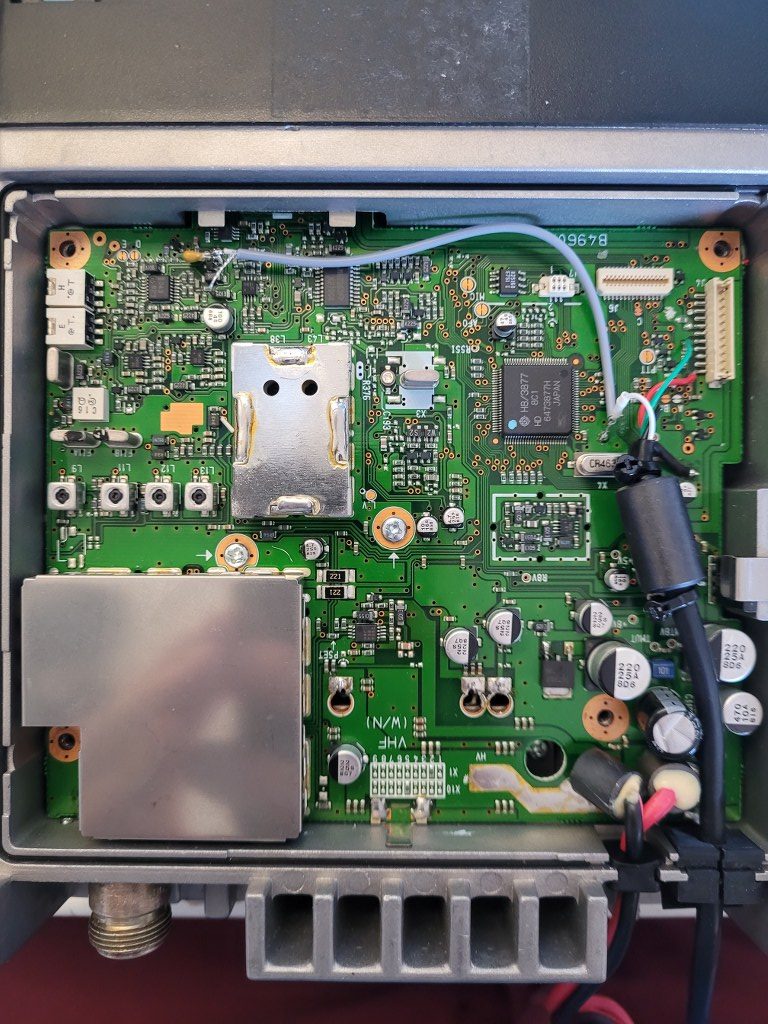
So I had to dig into the schematic and find a point where I could bypass that Pre-Emphasis circuit.
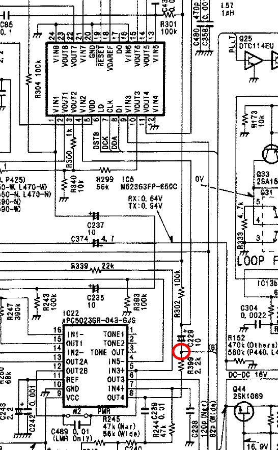
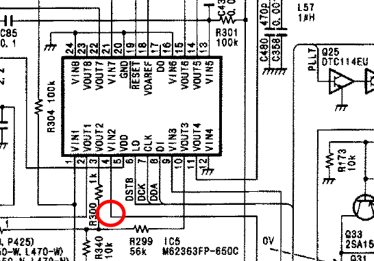
Measurements were taken at this point circled in red.
What needs to be said is that there are various models that are schematically slightly different. But the idea is simple.
Measure the signal between PIN 8 of the IC uC5023GR and PIN 4 of IC M6263FP.
When audio is offered via the AF input on the above connector, the MMDVM signal looks like this. (Distorted)
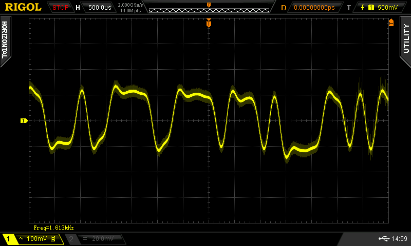
Now I knew that the MMDVM Audio presented on the AF input was distorted earlier in the circuit.
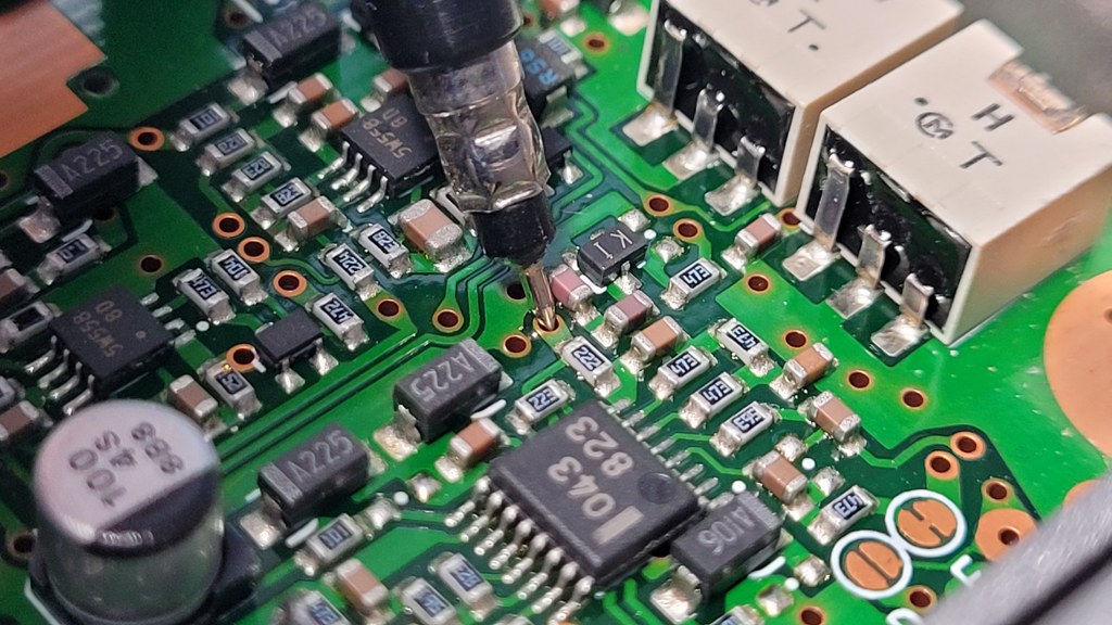
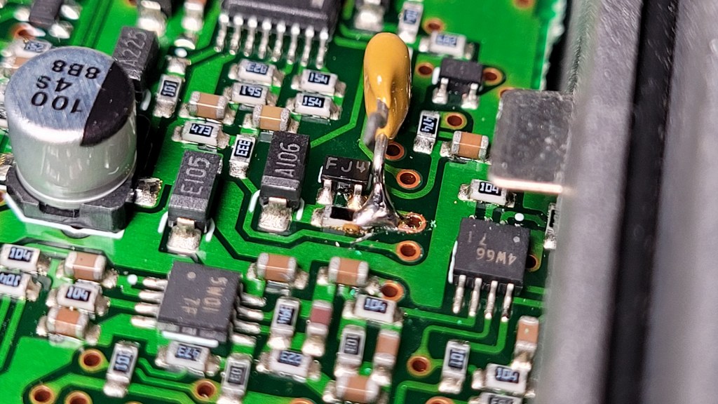
And that I had to offer the audio at the next point circled in red, after the filter circuit.
I did this with a 1uF capacitor.
When adjusting, make sure that the signal is neatly adjusted to 100mVpp
New point to inject MMDVM audio. This point goes directly to PIN 4 of IC M62363
If we now offer MMDVM Audio at the new point and adjust it to 100mVpp, the signal will look like this.
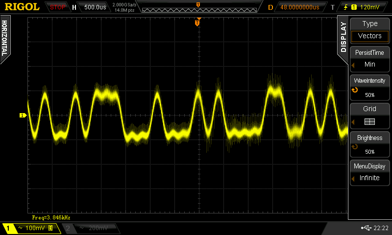
Now that this has been adjusted, the TX audio of the radio is perfect, and the BER on other received radios is 0%!
Overview of the connections
thanks for sharing it. I’m building an APRS digipeater and this helped me a lot