TUNER SOLD IN 2023
As I have succesfully built the ATU-100 kit, I decided to go for a beafier ATU kit.
Some weeks ago I received a kit from Ali Express.
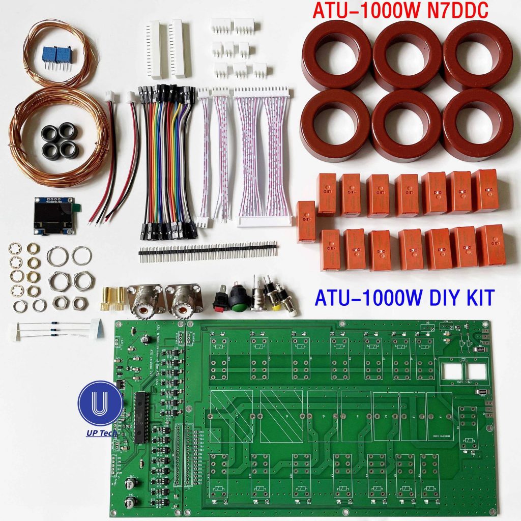
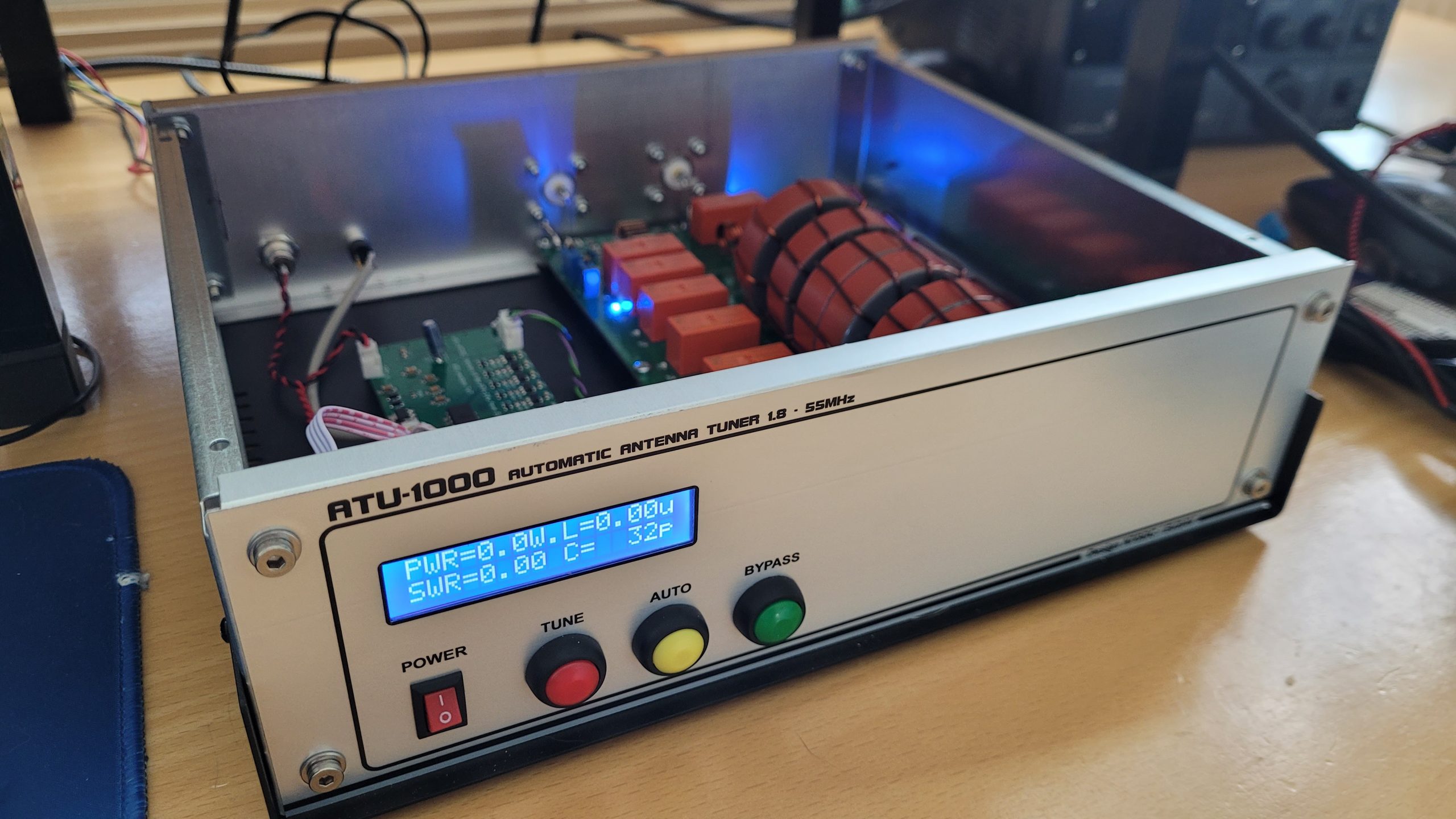
The ATU-1000 Automatic Antenna tuner kit.
It is based on the same design of N7DCC, but the board is designed by EU2AV.
The same firware is used as the ATU-10/100 firmware. but configured in EEPROM to match the ATU-1000 specifications.
All parts are inside the kit to fully build the tuner.
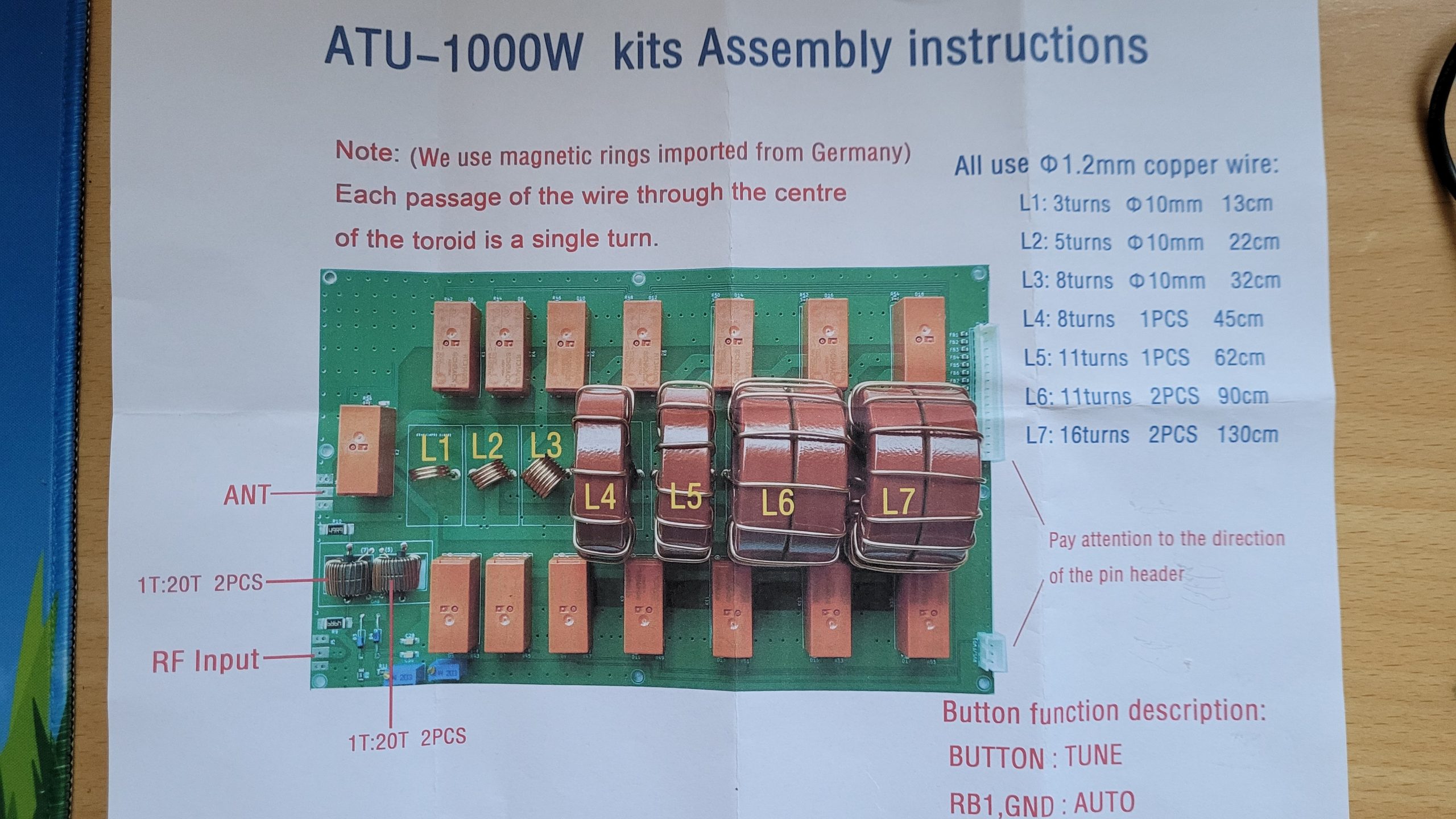
Nowhere on the internet were some building instructions easy to find. Fortunately, the kit came with a document with some directions on how to wind the coils.
I thought this was useful info, and something to share with you.
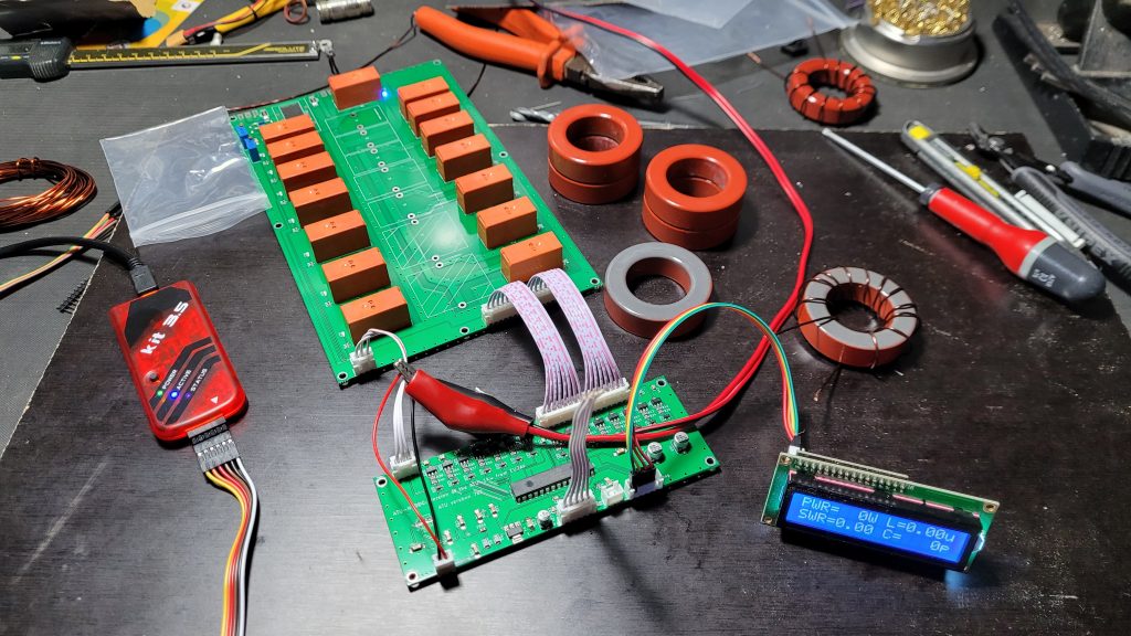
I was a bit sceptical about the genuinity of the T200 cores, but I have tested them compared to original Amidon T200 cores I have had lying arround.
And to my surprise there where genuine 🙂
Assembly was easy as all SMD and PIC Microcontroller where already soldered.
The only thing needed to do was soldering in all the relays and inductors.
I had already decided not to use the small OLED display. A large tuner needs a decent larger display 🙂
So I decided to use a 2×16 LCD.
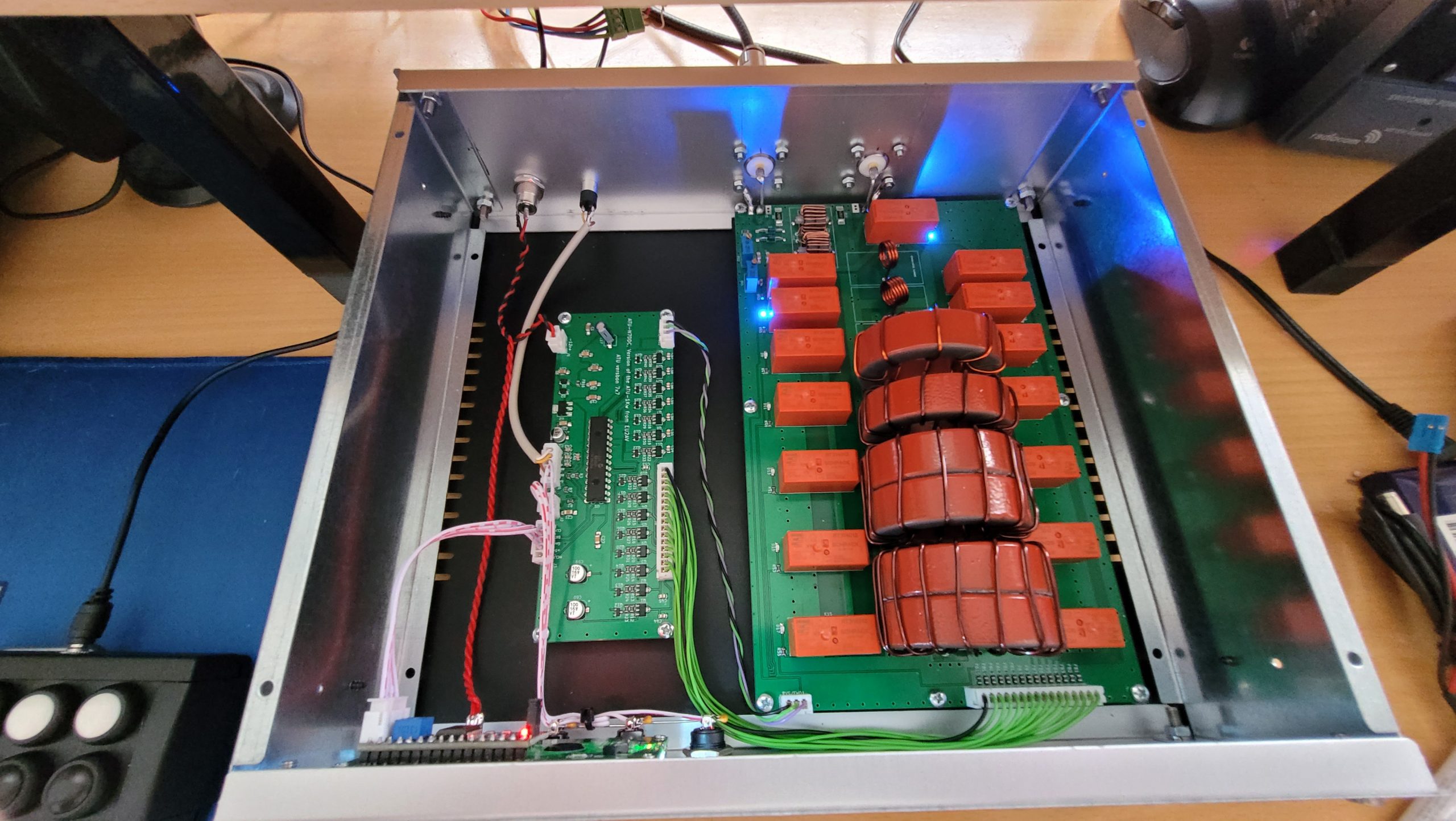
I had a nice case lying around, really perfect for this tuner. so this is done and the tuner is placed in this housing.
I just had to put the controller board somewhere else.I made new board connector cabling so I could place it next to the tuner board.
Not entirely unimportant was the design of the front.
Drawn in Corel Draw, and printed with a laser printer on special aluminum foil. and this foil sticked again on 2 layers of PVC adhesive foil. this is to make the foil as a whole a lot more rigid.
Furthermore, the print is finished with 5 layers of acrylic spray paint.
Things to do:
Improve SWR Bridge, sometimes it doesn’t measure the right SWR, especially with completely non-resonant antenna systems, it can sometimes indicate that the SWR is well matched. But in use, the SWR is al little bit too high on the higher bands.
Sold
Due lack of time any many other projects with higher priority, I have decided to sell the Tuner in its current working state.
Also I have inherited a lot of Ham radio gear in the last 2 years including some LDG and MAT tuners.
hello can i get firmware pic and eprom for atu1000 i have problem witch display probably code is broken in procesor it happen during work 14mhz
Hi Darek, I will try to look for firmware.
Yo he comprado un ATU-1000 montado y al recibirlo media mal y no acoplaba, simplemente conecté un medidor de calidad tras el atu1000 y ajusté los potenciometros para obtener la misma lectura de potencia y swr, ahora funciona perfectamente y acopla de maravilla.
I received ATU-1000 from Aliexpress some months ago, assembled it and tried several small modifications as follows:
– replaced 0.96″ display with larger 2.42″ OLED, works flawlessly
– desoldered PIC16F1939, mouted DIP28 socket to easily replace it as needed;
– wired 5pin female connector IN PARALLEL with OLED I2C connector, connected this to an “PicKit 3.5” clone (Aliexpress) programmer using ALL I2C 5 pins on the ATU-1000 controller board (GND/5V/DATA/CLK/MCLR(Vpp) ) – Oled Display uses only 4 of them, no MCLR. It works ! I could write/read blank PIC16F1938 using N7DDC firmware v3.2 and modify parameters (PicKit programmer v3.10). I couldn`t read original PIC as states “All Protected”.
To do: – measuring exact value of all coils / capacitors > modify EEPROM data accordingly and test results.
Does anyone have PWR/SWR calibration instructions for the ATU-1000. This would be regard to adjusting the two pots. Thanks in Advance
Does anyone have any information on how to calibrate the unit? There are two pots to adjust. Looks like one is for Fwd pwr and can set using a known input power. But how is the reverse pot adested?
Best way to calibrate the forward and reverse voltage is by using a 50 Ohm dummyload.
73 PA3VOS
Where is a reliable and quality source to buy this kit? 73 de KD6UYK (Tim)
Follow up: I found this kit on New DIY Tech. Love the cabinet and especially the lever display! Waiting for receipt of the kit and will need to compare the displays pin-in/out for the larger display. 73 de KD6UYK (Tim).
I have this Tuner , It doesn’t work automatically above 14 mhz, it’s ridiculous, it can’t lower the SWR, I tried it with different antennas,good work at 80-40-20 meters, I go to TEST mode and adjust it manually.
The sequence of coils values, which are much higher than the original sequence, are the ones to blame. It will do better on lower bands.
I have a kit recently bought, I will check it and I’ll probably use the original sequence of coils
I bought the same kit from AliExpress and the tuner is not suitable above 14 MHZ.
My antenna is a 43 footer vertical but I also tried a dummy load.
I have measured everything, replaced the diodes, calibrated the 2 pots for forward and reverse power but it’s behavior does not change.
The one thing that is a dead give away is that in bypass mode it introduces swr on a dummy load.
After playing with the test mode I came to the connclusion that the parts of the tuner alone introduce too much inductance that detunes the output enough at higher bands.
I also think that the tuning algoritm is wrong because above 21 MHZ it tunes to the lowest output which of course will produce the least reflected power voltage to the CPU.
I think that the algoritm should aim for the biggest difference between forward and reflected and not for best swr.
I suspect that almost all relay tuners have this problem more or less.
Update
After countless tests and modifications I found the problem(s) but unfortunately there is no easy fix.
The board itself has potential and it can tune a vertical with a 4:1 unun, it is the tuning algorithm that it messes things up especially when the transceiver’s ALC kicks in.
It goes for the lowest swr when in fact it should be aiming for the biggest difference of forward and reflected power with a limit of 2:1 or 2,1:1
For example full output is achieved with 1,56:1 but tuning stops at half the power at 1,4:1 due to ALC lowering the power misleading the tuner.
The other two big problems are RFI to the CPU board and the pic cpu itself.
I never understood why pic processors exist when for 8 bits there is the AVR.
Thf only solution since I don’t want to buy compilers etc and produce bloated code due to the pic architecture is to convert the CPU board to an AVR one, I am certain that it will work fine as the inductor-capacitor board was tested with 1 kw rf power on all bands.
Just because YOU don’t understand MICROCHIP PIC don’t knock them!
I want to begin this project but the thread above is a bit frightening.
Has anyone tried the fully assembled unit being sold from China?
Any word on the resumption of sales/support from original Ukranian developer?
Any advice on beginning my KW ATU journey would be appreciated.
Neil, NYC N2EYE.
Hi, could anyone please send me the assembly Instructions as PDF?
(ATU-1000 DYI)
I lost mine, have only the 1st Site.
Thanks in advance!
BR Andi. DL2IAQ
I had also a plan to buy the 1 kw kit , but I want the tuning part outside close to the antennes
But the first kit I thought it’s doable
But if I see this PCB then I have to bring more then a few wires
First was thinking 2 wires for 12 volt for relay and for the difficult things in that blackbox with many pins
1 wire to start tuning
2 wire to stop button
But is it possible with 6 wires to control the unit
Any help is being appreciated
Thanks to everyone who takes the time to read my bad English and help me
Please do share with us the recommended upgrade diode for the SWR Bridge. The genleman on Youtube suggests using 18 gauge solid wire inserted into the out jacket/insulation of a 30,000 volt wire [ignition wire for spark plugs maybe]?
Where might I purchase a good quality larger LCD screen?
Last, thank you everyone for your help!
AJ6XW
SWR Bridge
Ive heard there is a recommended diode upgrade in the SWR Bridge circuit. Are you aware of this and can you comment?
73’s Ka4upw
Hi, No I did not read about it yet.. any source where you read this?
Hello,
I have a problem with the ATU1000 not working in bands above 18 MHz. I was advised to try to update the firmware. Unfortunately I don’t know where on the finished panel the PIC programmer should be connected. Thanks if you can help.
Is it possible to use the tuner outside (closer to the antenna) and the control unit inside the house? The connection would be with shielded cables.
Excellent, well done…! Now print out a copy of the eprom contents from the high power atu firmware you downloaded, then compare it to your working eprom code….
In the original atu-100 documents it explains which “eprom cells” hold the power settings etc etc. Simply copy the appropriate settings from the high power firmware into your working code.
Have fun Paul
Hmm, interesting!
As a test how about copying the code from your working atu-100 and trying the board with that code ? That should prove conclusively if your control pcb for the ATU-1000 is at fault.. it just means for now all the eprom settings etc are for a 100 watt atu. If the pic is faulty they only cost a couple of Dollar’s to replace,
Regards Paul
HI PAUL!!!
THAT’S IT, ADVERT ON!!
THANKS VERY MUCH !!
BUTTON Goes Tune and Reset, the other buttons work too!
– What do I have to change now for the ATU-1000?
vy 73 Manfred
.. ps. code all testet 7E,78,7A,4E
Hello,
Thank you for your patience,
the OLEDs are ok, I tested them with an ATU-100, I always look closely at the connections.
With the programming switch there is always a relay at the beginning and end, the current goes from approx. 50 mA to approx. 0 – and then to 50mA, on the PIC board it is approx. 10mA.
I’m at a loss.
vy 73 Manfred
Hi Manfred,
Don’t panic. Theres been a few of those Oled boards faulty, including mine. It sounds as if your board is “booting up” as the relays are resetting to default.
First check, is the Code set for Oled or LCD display ! I think from memory the code at that link was for a LCD display….at this point in time the buttons won’t actually do much…..infact the only reaction to pressing the buttons at present will be to change the display to indicate the mode its in… and as your display isn’t working…. if your able to program the Chip, and get a good verification from your programmer, I’d think the Pic is probably ok…AND of course the programmer uses the same plug and data lines as the display does. Try a standard LCD display with a serial to parallel interface …don’t forget to set the correct eprom settings fir the dispkay
Regards Paul
I don’t have any more advice, can the PIC be defective, unfortunately I can’t write a test program for it, or can I exchange the PIC?
The display shows GND .5V: CLK + DAT with a square-wave signal of 5V intermittently, the buttons do not react,
after switching on, all relays go on briefly, then only one R2. (blue LEDs)
see only one possibility _ change PIS…???
lots of non-working counterfeit PIC’s this is a big problem
–m strange, programming works -reading too
0000 31A8 2D3B 3FFF 0029 083A 3A00 1903 2821
0008 0021 170D 3006 00FD 0BFD 280C 0000 178D …
but the display is off and no button works..
73
oo TNX Version 2.7 ok
TNX
Hello,
After switching on the voltage, all relays switch briefly, then Rel 2 on, no reaction to the tuning button or the others.
Code-Protect, m .. but if nothing responds..
vy 73 Manfred
Try tnis link for firmware
https://www.ur4unr.com/2021/10/15/atu-1-5kw-n7ddc-mode-by-eu2av/
Regards Psul
Hello,
GREAT, there is almost no information about the ATU-1000.
– well I also got one from Aliexpress, – UNFORTUNATELY the PIC is EMPTY – all 00000, ((everything is readable in the ATU100, I need the soft, where do you get it.))
PIC16F1938 and 0.96″ display (4 lines).
by 73! DL2AMM Manfred
for ATU-1000
Hmm are you sure its not got the code protect set ?
My kit arrived in that state,
I’ve started to edit the new version 3.2 code for 1Kw use
Regards Paul
Hi pd5dj, can you offer me your Atu 1000W case ? Or were can i buy it ?
Your case looks perfectly and very good!
dk9wf, Fred
Hi !
Do you have a picture of bottom PCB ??
i have buil the same unit, but i think that the capacitor presoldered onboard are not as the schema..
the scheme report 10p,22p,40p,82p,160p,320p,640p
but my measure on soldered capacitors report : 30p,100p,160p,330p,750p,1650,3500p
Can you measure yours capacitor for me ?
Tnx !
Hi, Sorry not at the moment.
When I will take the tuner apart again, I will take pictures.
Hello, I wanted to know if the 6 Toroids are T200 Amidon or T68-2 ? Thank you
Hi Roberto, these are T200-2
I finally had some time to retrieve the firmware + eeprom settings from my unit.
You can download it here: https://www.pd5dj.nl/wp-content/uploads/firmwares/ATU-1KW_04-11-2022.hex
Right Click Save as
hello, I downloaded your file but it doesn’t work for me, I have a pic 16F1938 and a 1602 LCD, do you know where the error could be? The older one works thanks Franta 73 OK2W
Hello pd5d
whats the version of FW you are using ? I am facing some problems with tunning.
Can you send me also your hex to compare ?
73 de OE9SAU
Hi.
I have the same Tuner.
Is there any changes for usind a 2×16 LCD?
My extra LCD shows no numbers or letters. Only light
73 Matze DO4OD
Hi Matze
You will have to edit some adresses in the firmware EEPROM section.
https://github.com/Dfinitski/N7DDC-ATU-100-mini-and-extended-boards/blob/master/ATU_100_EXT_board/ATU-100_Extended_Board_User_Manual_eng.pdf
Check if Addresses:
00 = 7E or 78 or 7A (for a PCF8574AT adapter) or 4E (for a PCF8574T adapter)
01 = 01 (1602 LCD)
I still have to open up my tuner to add a Ground point at the back.. I can make a dump of my hex file and sent it to you if you like.
Hi Bjorn.
That would be fine!!!!
do4od@darc.de
Do you have temperature problems with the SWR Bridge ( the 2 Cores get very very hot with more than 100 Watt´s)
73 Matze
Hi,
That’s very interesting because I am facing some difficulties with this auto tuner…
First of all, the bypass relais is always actuated and the RB1 grouding has only effect on the display (_) but the relay stays in the same position.
Finally, I have remove the 2N7002 which command this line.
Tests are in progress…
Regards
Это не байпасное реле. Это реле переключает контура для значений больше 50 Om, и меньше 50 Om.