A friend of mine Gertjan PA3FZB who is crazy about 3.5m broadcast “amateur” stations 😉 recently came up with an article about a HB9CV design for 3.5m. He asked me if I could build it for him. and so it happened 🙂
On the internet there is a very handy calculation tool to calculate an HB9CV: https://www.changpuak.ch/electronics/HB9CV.php
Since I’ve been building antennas my entire amateur career, I had some idea how I wanted to put them together.
I CAD-drawn the entire antenna, using commonly available materials.
Boom measurement = 25x25mm approx 800mm long.
Elements are made from 12-13mm diameter.
Phasing feedline is made from 6mm2 / 2.6mm diameter copper wire.
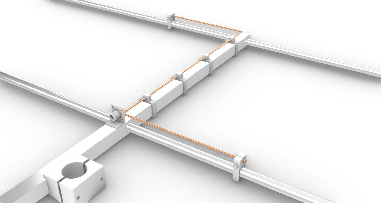
The Phasing feed line is clamped with 3D printed clamps.
High enough to ensure rain droplets wont “short” with the boom itself.
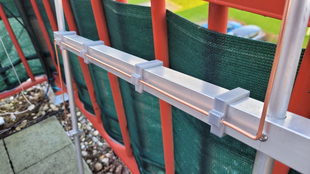
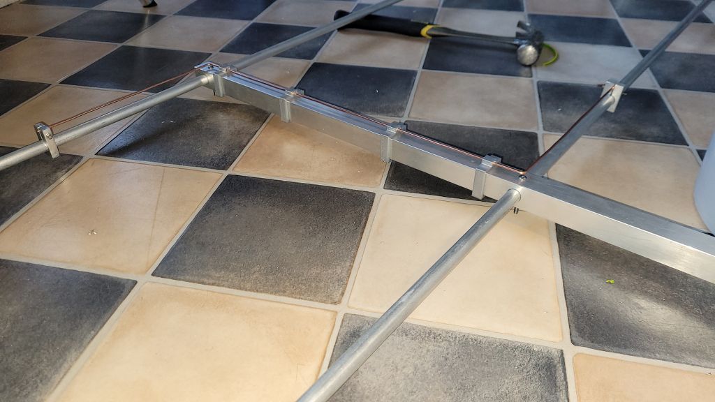
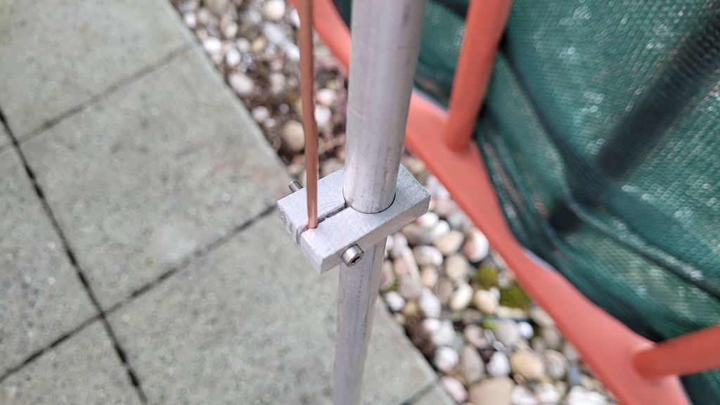
A simple method I used to clamp the Element to the phasing feedline wire to create the Gamma-Match principle, is by taking a 8mm think piece of aluminium drill holes with the exact measurements of the feedline and element diameter and saw a slit through both holes.
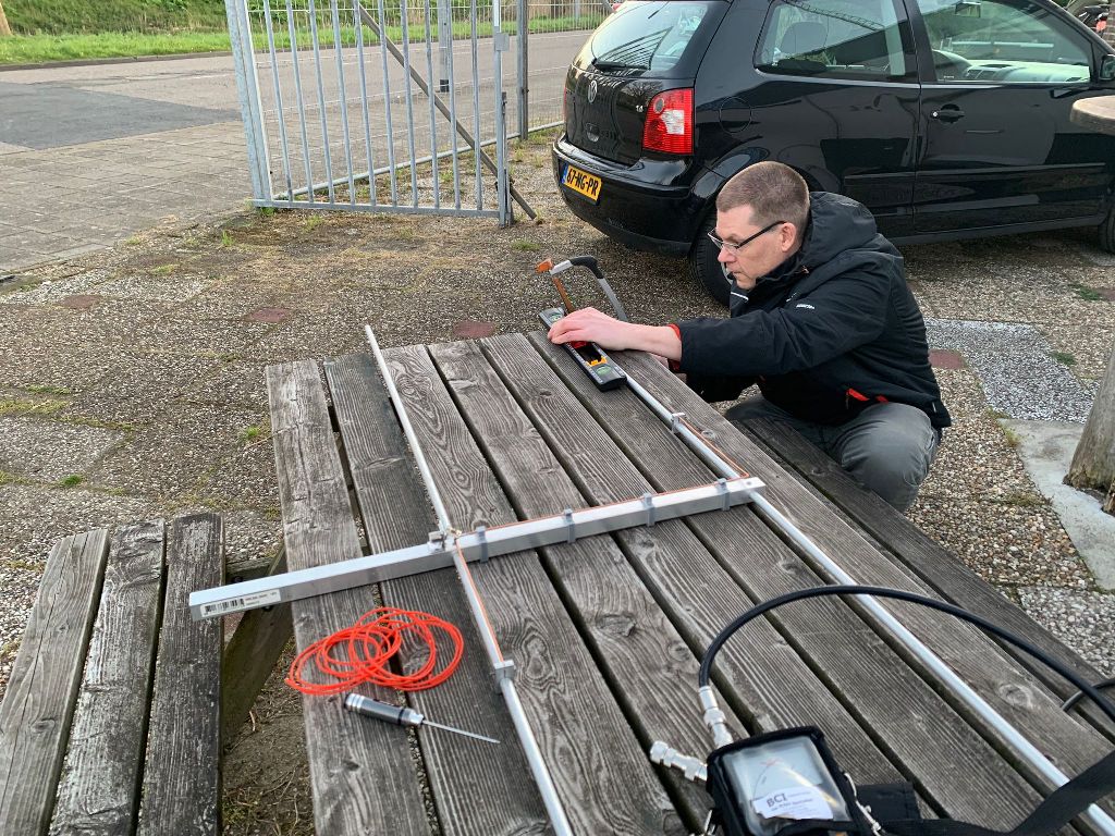
Antenna almost completed, only thing needed is to obtain the right amount of capacity between GND and Phasing FeedLine at the connector.
Added a variable capacitor at the feedpoint we could determine the correct value for a correct impedance match. The only thing needed was to cut the elements to the right resonant frequency.
What I noticed while shortening the elements was that what we sawed off was exactly the length that was not included in the calculator. The shortening factor of the alumium. If we take the calculated length of the L1 or L2 again with the Vf +/- 94%, then the calculated difference was exactly the sawn-off piece of the element 🙂
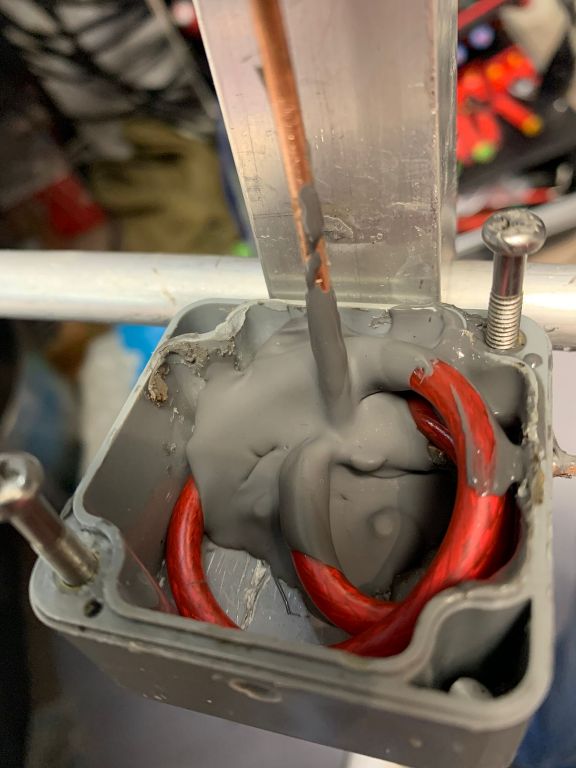
Here the variable capacitor is replaced by a coax style capacitor. and sealed with plastic-dip.
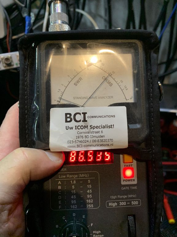
Thats what we wanted too see, a perfect SWR and Resonant at approx 86MHZ
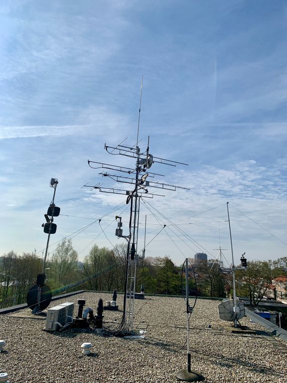
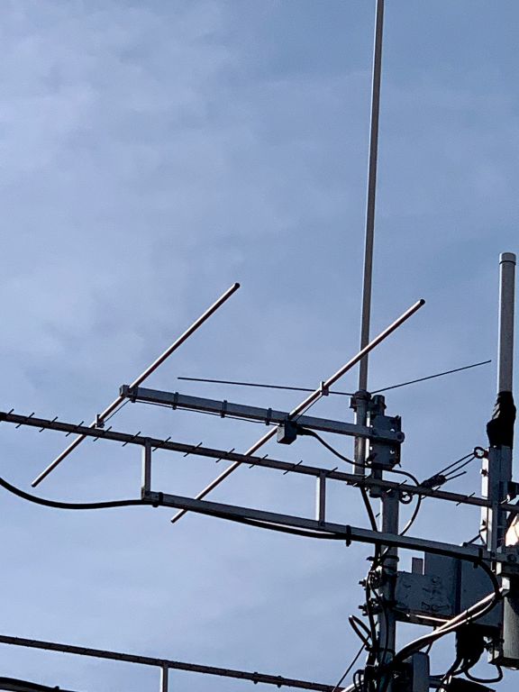
Antenna placed in top of the mast @ PA3FZB and doing its job nicely 🙂