Last week I have constructed a new antenna system for HF operations.
3 Years ago, I started with a 2 band FAN Dipole. for 10m and 20m.
I have enjoyed operating with this antenna very very much.
The only thing that was bothering me was that I could not operate on 40m.
The lack of available space for such wide antenna was not there.
I have tried to add a 40m dipole on the existing FAN Dipole, but it always gave problems, detuning the system when there was wind, or even when the evening kicked in. the antenna would detune badly on 40m, due the change of weather in combination with my situation on the apartment.
Therefore in the beginning of 2017 I started to use a maxed out dipole of what I could place.. 2x9m with 450ohm feedline.
This way I could operate all the way from 40m to 10m, with my tuner.
Finaly I could operate on all the bands :-), and It worked really good!.
Well…….
It worked great, But a month ago I started to notice something.
I know the bands are really dead most of the times due the solar minimum, but I always could work South America in the evening on 20m with my Fan Dipole.
With the 2x9m dipole with feedline, this was another story.
I hardly could hear them, and therefore hardly work them.
I took out my old Fan Dipole and hooked it up, and voila, South America stations where back online!
I Figured out that the 2x9m dipole was too long for proper 20m operation, the radiated lobes are very different of that of dedicaded 20m dipole.
Well now, what to do???!
I Surely didnt want to go back to my 2x9m dipole, and didnt want to use my 10/20m Fan Dipole in it’s dualband situation only.
No option was to add a 40m dipole, because my experience with that was not very good.
TRAPS!
Yes traps.
I thought, If I could manage to add 20m traps on a 10/20m Fan dipole, the 40m portion would be somewhat shorter that a conventional dipole.
Maybe I can place this?
Eureka!
I did not want to modify my old Fan Dipole, instead I have made a completly new one.
The biggest challenge was making the traps for 20m.
All over the internet I read about Trap designs, but one thing was not very clear.
What frequency is best to tune too?
Some people tune these traps, resonating somewhat beneath the lowest bandlimit,, for example 20m.. 13.9mhz.
Until today I did not find “proof” why this should be tuned there.
Others tune them exactly on the higher bandlimit,, for example 14.350mhz..
And others tune the way above the highest bandlimit. for example 15mhz! like ON7EQ http://www.qsl.net/on7eq/projects/coaxtraps.htm
After reading some more about coax traps, It all made a bit of sense.
The traps, are like absobers for the frequency they are designed for.
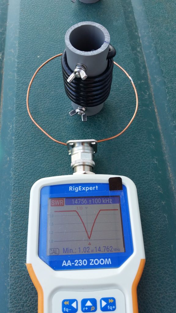
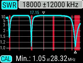
On the picture below you can see the dip is starting to “fade in” from a high impedance to the dip low impedance, and after the dip it is “fading out” back to a high impedance.
You can imagine when a trap like below, operating at 14.7mhz, the impedance of the trap at that frequency is very low.. so lots of current is running through the trap.
Yes… you guessed it, I will get HOT! and melt the trap.
I decided to go and sit in between 14.300 and 15mhz,, 14,7mhz..
This way, when operating at max band limit 14.350mhz the trap does not yet starts to absorb energy.
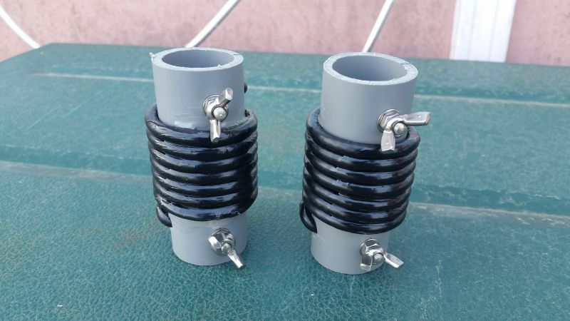
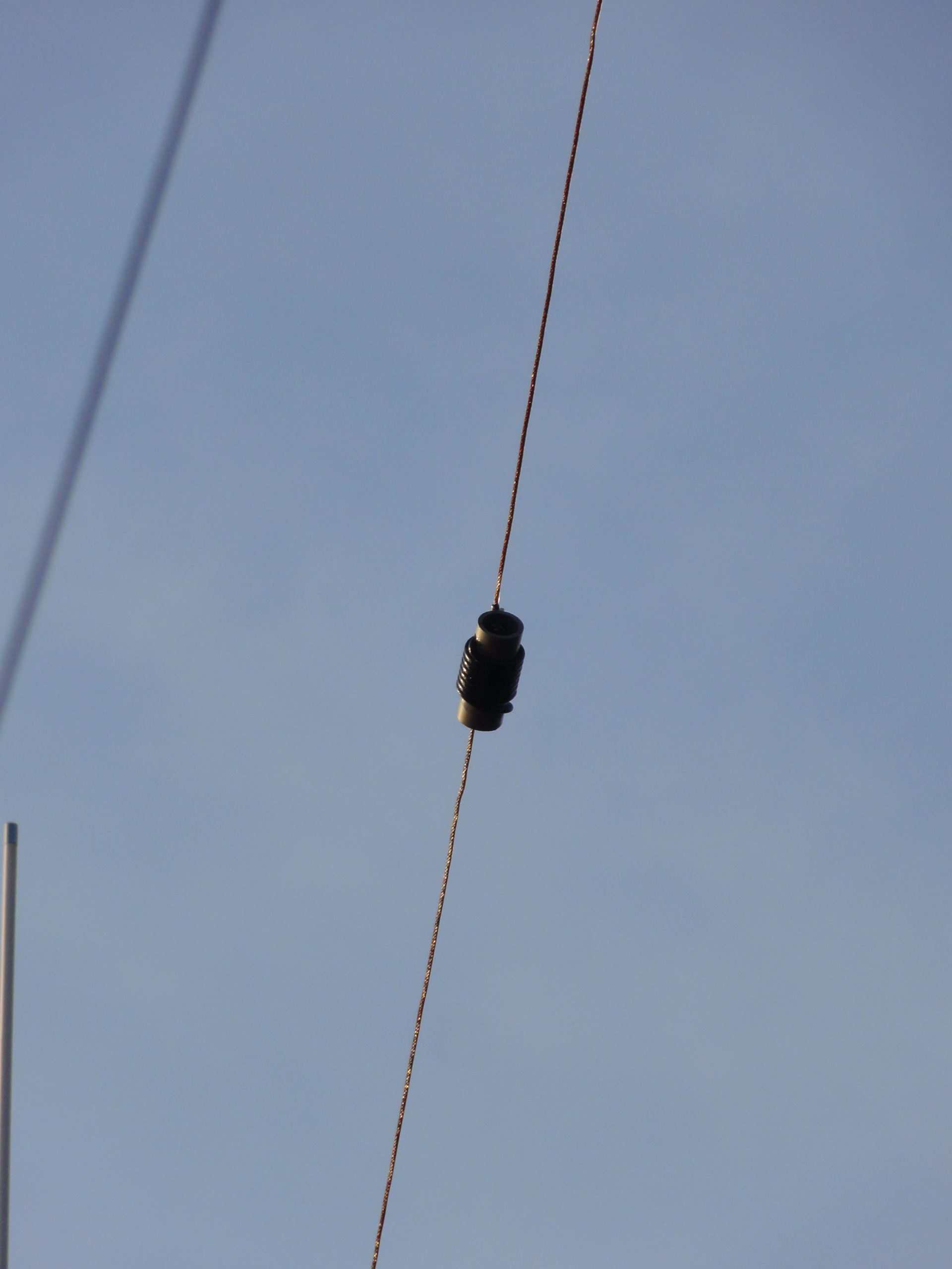
After some tuning 2 fine traps are done and ready to go airborne 🙂
I have fixated the windings with PVC glue.
And all the solder ends inside are coated with UV protected glue.
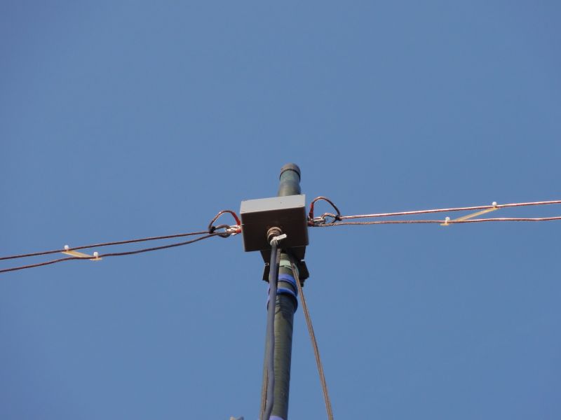
Balun box, consisting of a 1:1 Balun with an FT240-43 Core, 2×7 winding of RG58 Coax.
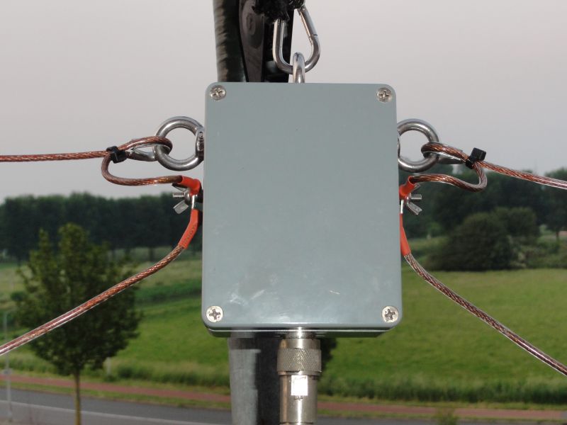
Mounting of the Dipole wires for 20(40)m and 10m.

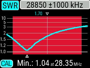
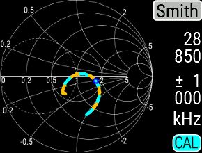
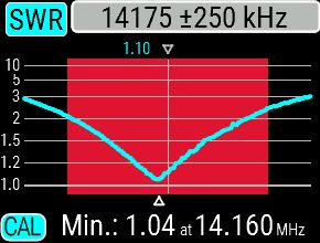
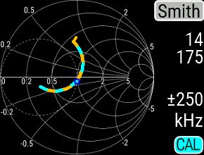
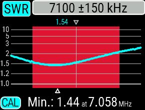
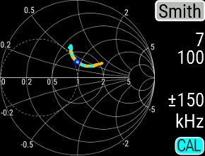
After some evenings of tuning I have came to great results, showed below.
| 10m | |
 |
 |
| 20m | |
 |
 |
| 40m | |
 |
 |