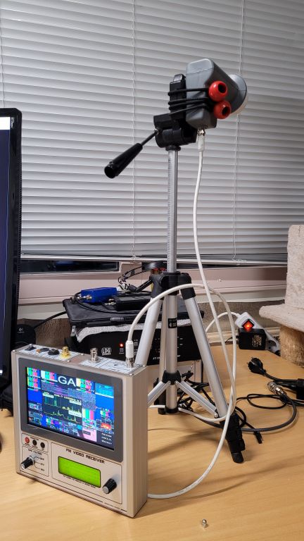
A while ago I came up with the idea of building a portable ATV receiver.
Important features of this receiver had to be:
1. Large screen with real noise (no fake noise)
2. Of course with built-in battery with builtin charger.
3. PE1ICE MiniATV receiver as base.
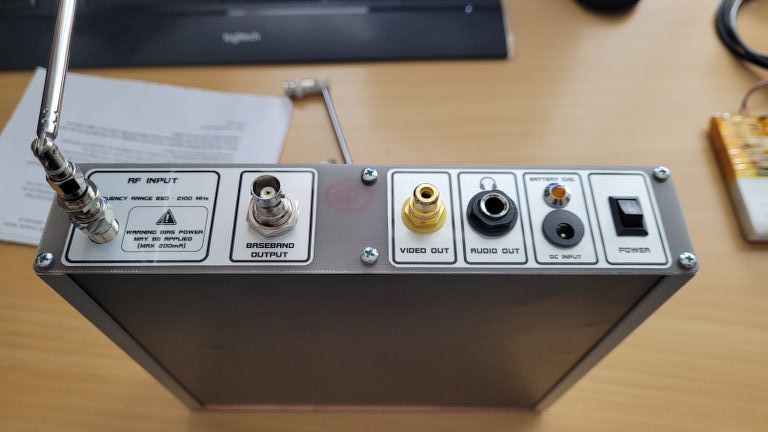
4. Switchable bias voltage. 12/18V, and OFF.
5. Video and Baseband outputs for testing purposes.
6. Headphone output for Nicam/FM audio.
7. Possibly built-in speakers in the future.
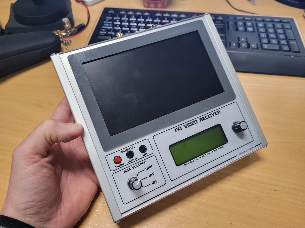
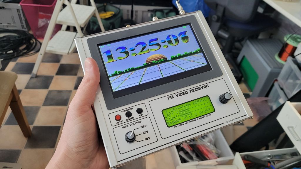
Video Monitor
I had an old FPV screen lying around and the internal battery had died.
The Boscam RX-LCD5802, Still available today.
This Monitor has real noise, no artificial static noise generator.
So this is perfect for picking out the smallest signals.
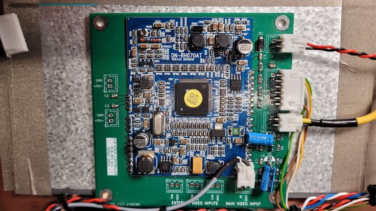
The heart of this FPV screen was a universal adapter board, which was soldered to a custom I/O board.
After some measuring work I discovered that it was very simple to control this board and use it in such a way that AV-IN is always active.
I made a new I/O board for this board. which also includes a buffered video splitter. So that I could also send the video signal outside immediately.
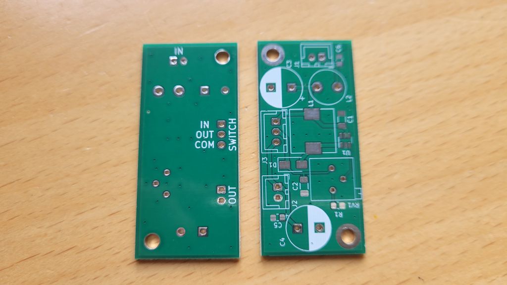
Battery Charger
I also found the BATTERY charging section on the old I/O board. This is based on a CN3702 Lithium charger IC. 2 stands for 2 cells.
I thought this was a very nice IC and it was also easy to obtain.
I saw that this was also available for 3 cells. The CN3703.
Since I wanted to run the system on 12V, I could use a 3s2p configured LiIon 18650 cell pack.
I have also drawn a nice compact universally applicable PCB for this charger.
There are 3 connectors on the PCB.
DC IN, Output and Battery.
It is important that the battery is equipped with a BMS (Battery Management System).
As soon as DC-IN is connected, this voltage is immediately bypassed to the output, and the battery charger is switched on and charging takes place.
If no DC-IN voltage is present, the battery is automatically bypassed to the output.
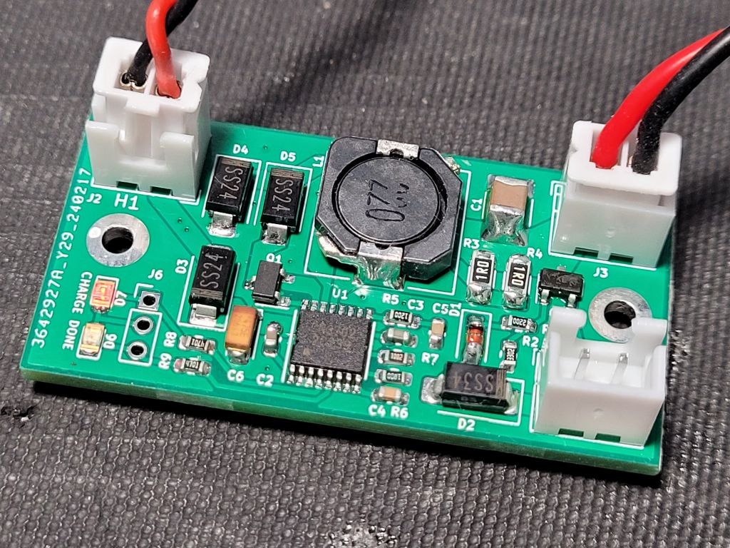
In my case I am using the 3s version CN3703.
If DC-IN is connected, the charger will charge according to a charging curve especially for Lithium batteries.
If the voltage is below 12V the charger will become active.
The maximum charging current can be set via the resistance value of the shunt.
I set this to 1A.
An LED indicates that the charging cycle is complete, and another LED indicates that it is charging.
I mounted this last LED on the back panel.
Handy for many other purposes.
Bias power Step Up Converter
I also drew a PCB for a DC-DC StepUp converter.
This was necessary to make the required 18V from <12V.
This is based on the well-known MT3608.
However, I have applied some extra DC filtering to this to ensure that there is no noise on the 12v system.
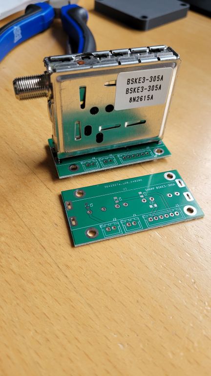
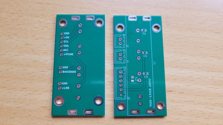
Breakout board for the SHARP BSKE3-305A Tuner
Because I was drawing PCBs anyway, I also drew a nice universal PCB for SHARP BSKE-3-305A Tuners.
It has 3 seperate connectors:
- Power Supply + I/O control
- BaseBand signal output
- Bias Power Supply
I have also added a small PTC SmartFuse of 200mA for shortcircuit protection.
When using the Receiver with any other than LNB’s, like for example a Cloverleaf.
These antennas have a full electrical short.