GS-232B Antenna Rotator Simulator — Azimuth & Elevation on an Arduino Nano

Background
I am currently working on a project called Rotor Server for N1MM — a server that manages multiple antenna rotators and makes them available to the N1MM contest logger. I am building this for the PA6Y contest station. The server runs on Linux and includes a fully automated mode with wind protection: it monitors wind speed and automatically parks or stows antennas when conditions become dangerous.
To develop and test all of this properly, I needed a way to simulate a large number of rotators simultaneously.
Buying ten physical rotators with interfaces was not really an option. So I had to get creative.
The one constraint was that each rotator interface connects to a serial port — that part had to be physical. But everything behind it? That could be simulated. What I needed was a device that plugged into a serial port and behaved exactly like a real GS-232B rotator controller: responding to commands, reporting positions, simulating the ramp-up and ramp-down of a real motor, and even triggering stall detection when movement stops unexpectedly.
This simulator does all of that.
What is this?
The GS-232B Antenna Rotator Simulator is a small device built around an Arduino Nano that behaves exactly like a real antenna rotator — without any moving parts. It connects to your PC via USB and responds to the standard GS-232B rotator protocol, the same protocol used by software like Ham Radio Deluxe, MacDoppler, and SatPC32.
The device is ideal for testing and configuring rotator software when no physical rotator is available, or when the antenna installation is not yet complete.
Azimuth and elevation
The simulator supports two independent axes:
- Azimuth — full 360° rotation, clockwise and counter-clockwise
- Elevation — 0° to 180°, up and down
A small switch on the board selects the operating mode at power-up:
- Switch closed (pin D2 to GND): azimuth + elevation mode
- Switch open: azimuth only
Supported commands
The device responds to the standard GS-232B command set over serial at 9600 baud:
| Command | Action |
|---|---|
C |
Report current azimuth |
C2 |
Report current azimuth and elevation |
M xxx |
Rotate to azimuth xxx° |
W xxx yyy |
Rotate to azimuth xxx° and elevation yyy° |
L |
Rotate counter-clockwise to 0° |
R |
Rotate clockwise to 360° |
U |
Elevate to 180° |
D |
Lower to 0° |
A |
Stop all movement |
E |
Stop elevation |
Realistic movement
Movement is not instant. The simulator ramps up from a slow start, cruises at full speed, then slows down again as it approaches the target — just like a real motor-driven rotator. There is also a short one-second delay before movement begins, simulating the time a relay takes to engage.
Position memory
The last known position is automatically saved after the rotator has been stationary for a few seconds. On the next power-up, the simulator starts from that saved position rather than zero.
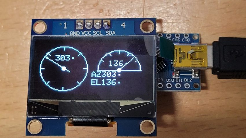
OLED display (optional)
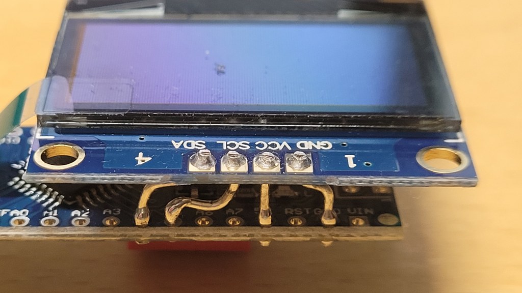
A small 128×64 OLED screen can be connected via I²C (SDA to A4, SCL to A5). It shows a live view of the current state:
- Left half: a compass rose with a needle pointing to the current azimuth
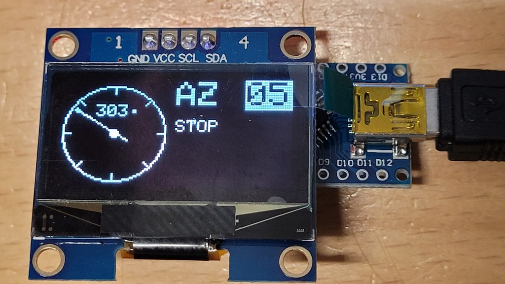
- Right half: an elevation arc with a needle (in AZ+EL mode), or a larger azimuth readout with direction and speed (in AZ-only mode)
The display also shows the current speed in °/s while moving, and counts down to the next position save.
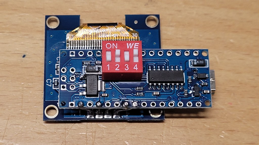
Unit ID — identifying multiple simulators
If you run more than one simulator at the same time, you can assign each unit a number from 0 to 7 using three small switches. The ID is displayed on the OLED so you can immediately see which unit is which.
The switches are wired between pins D3, D4, D5 and GND. Closing a switch adds to the ID:
| ID | D5 | D4 | D3 |
|---|---|---|---|
| 0 | open | open | open |
| 1 | open | open | closed |
| 2 | open | closed | open |
| 3 | open | closed | closed |
| 4 | closed | open | open |
| 5 | closed | open | closed |
| 6 | closed | closed | open |
| 7 | closed | closed | closed |
The ID is read once at power-up. Changing the switches takes effect after a reset.
Hardware overview
| Microcontroller | Arduino Nano |
| Connection to PC | USB (serial, 9600 baud) |
| Display (optional) | 128×64 OLED, I²C (SSD1306 or SH1106) |
| Mode switch | D2 to GND = AZ+EL, open = AZ only |
| Unit ID switches | D3, D4, D5 to GND |
Preventing reset on connect
Some rotator programs (and serial terminals) briefly toggle the DTR line when they open the serial port. On an Arduino Nano, this DTR signal is connected to the reset pin via a small capacitor on the board. The result: every time your software connects, the Arduino resets — and the program may time out before the device is ready to respond.
To prevent this, remove the 100 nF capacitor between the DTR line and the reset pin after the firmware has been flashed. On most Arduino Nano boards this is a small SMD capacitor labeled C4 or C5, located near the USB connector.
Important: once this capacitor is removed, the Arduino can no longer be reset automatically by the upload tool. To flash new firmware you will need to press the reset button manually at the right moment during upload, or temporarily bridge the capacitor pads to restore auto-reset.
Who is this for?
- Radio amateurs setting up satellite tracking or antenna pointing software
- Developers building or debugging GS-232B compatible applications
- Anyone who wants to test their rotator setup before the hardware is in place
Download & source code
The firmware is available as a PlatformIO project. Open it directly in VS Code with the PlatformIO extension installed, select your board and port in platformio.ini, and hit upload.