Some people asked my some questions about how to properly connect my Rotator interface to their rotators.
Most common questions are:
- My rotator will not rotate back when rotation is at max position.
- I have got distorted readings on the display.
How to properly connect the rotator interface to a rotator
In this part I will describe why the rotator is not rotating back again, and how to fix this.
The reason why some rotators are not rotating back is because they have endswitches.
These switches protect the rotator rotating over their max mechanical rotating limits when operating.
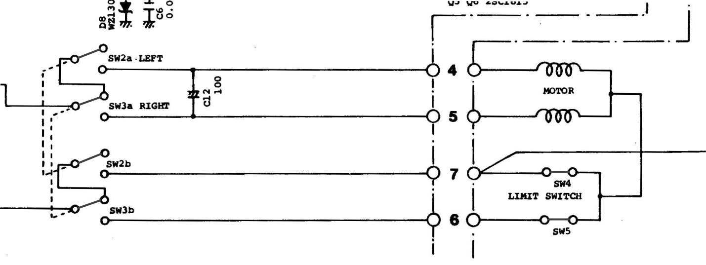
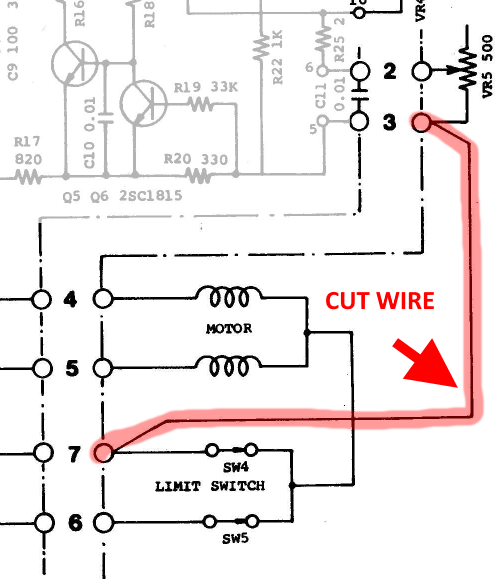
This is the OFF situation when no Left or Right button is pressed, and the endswitches SW4 and SW5 are not made yet.
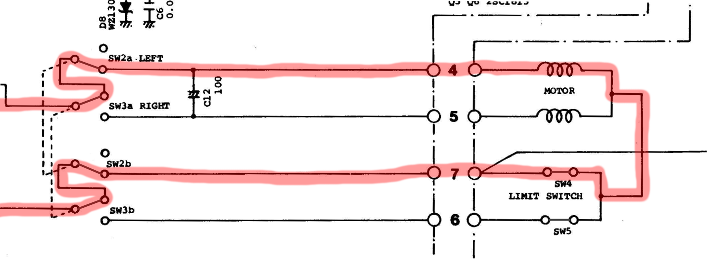
When the LEFT (CCW) Button is pressed with SW4 still closed we can rotate until the endswitch SW4 is hit.
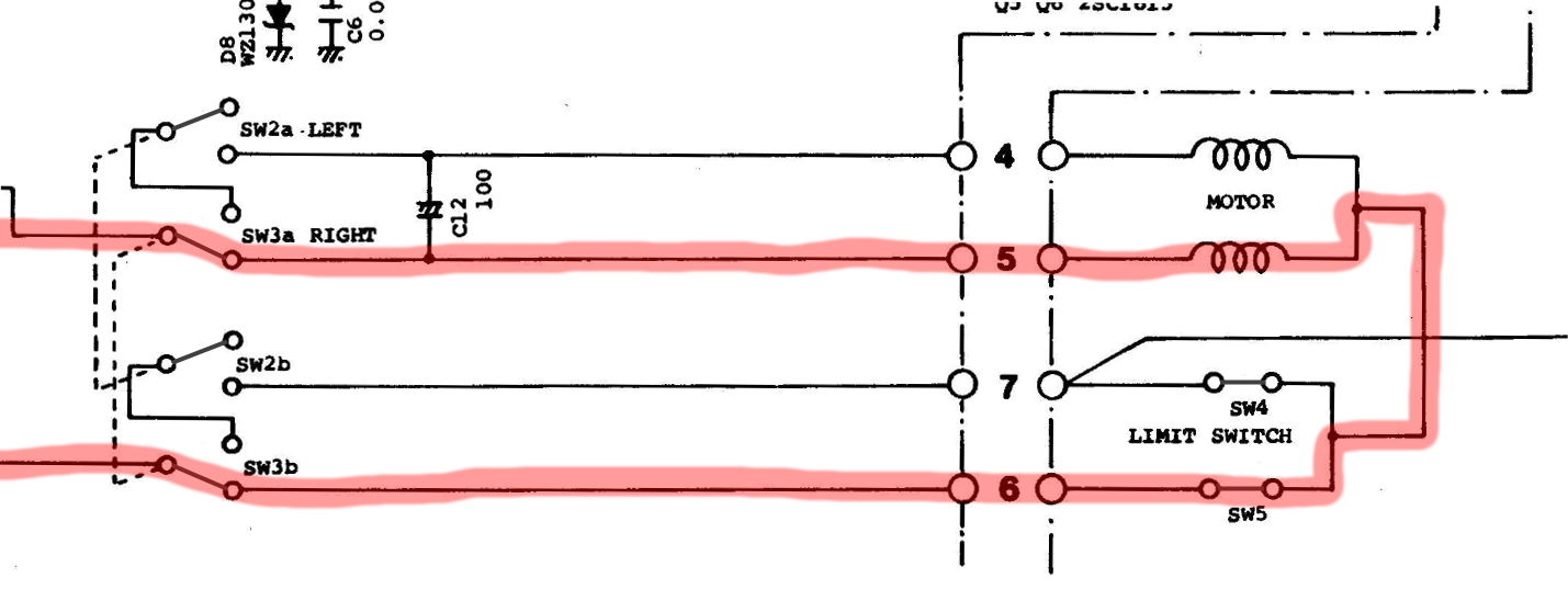
Same goes for RIGHT (CW) Button, if pressed with SW5 still closed we can rotate until the endswitch SW5 is hit.
When rotating RIGHT (CW) and the endswitch SW5 is hit, SW5 will open up.
And the current flow is broken. Pressing RIGHT (CW) will not work any more.

Because SW4 is still closed, the LEFT (CCW) button is the only way to rotate back again.

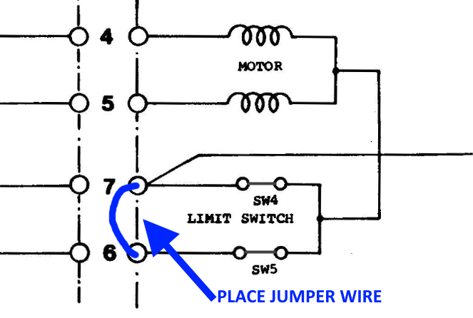
All this is possible because the internal switches of the Rotator control unit uses double pole switches for each direction.
Because the Rotator interface has not double pole switches only a single switch solidstate relais we need to slightly modify the rotator wiring.
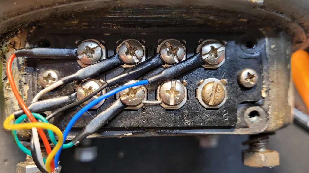
The modification is pretty simple. We just have to place a jumper wire between terminal 6 and 7 at the rotator.
In this case the endswitches are bypassed.
The only disadvantage of this method is that we disable the protection circuit.
But because we are using the rotator interface, that has built in rotation protection, rotating will never be possible below 0 degrees (Max CCW) and 360/450 degrees (Max CW).
Jumping distorted readout of position
One of the major reasons with distorted readouts of the position are because some rotators have a internal jumper between Terminal 3 and Termimal 7.
While you have never seen any issues with your normal analog rotator controller, digital rotator controllers will show you every slightest change in voltage coming off the internal potentiometer while rotating.
The better the potentiometer inside the rotator the less you will notice any distortion.
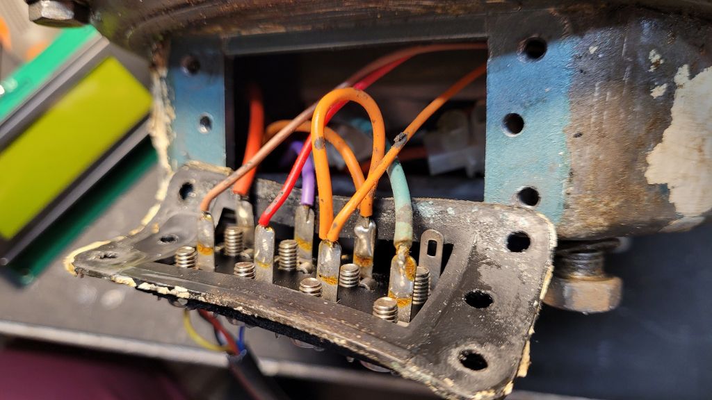
Now in some rotators AC Common wire of the motor (Terminal 7) is connected internally with a jumper wire to the DC GND (Terminal 3).
This saves a wire in your rotator cable, since AC and DC can run over the same cable.
But in a “digital” case, noise coming off the AC common wire while rotating, can add noise to the DC Ground.
So in this case it is always better to connect the internal Potentiometer (Terminal 1,2 and 3) with seperate wires. So AC common and DC Ground have their own seperate current paths.
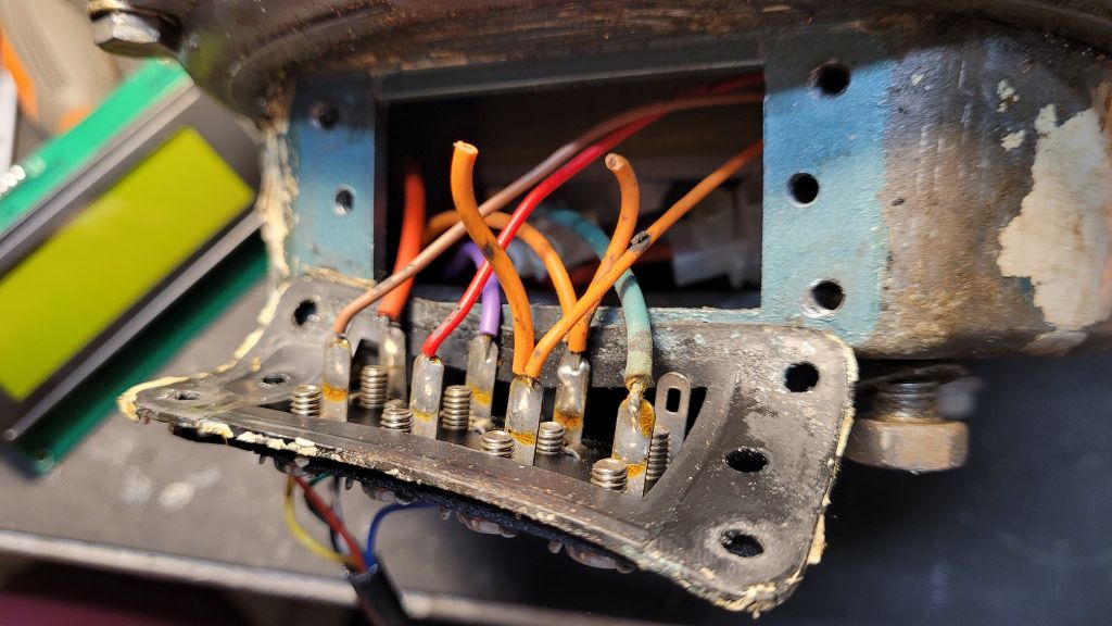
The only thing you have to do is cut/remove the internal jumper wire between Terminal 3 and 7 and you are good to go 🙂