Some time has passed, and a lot has been done so far.
Construction Tuning Section
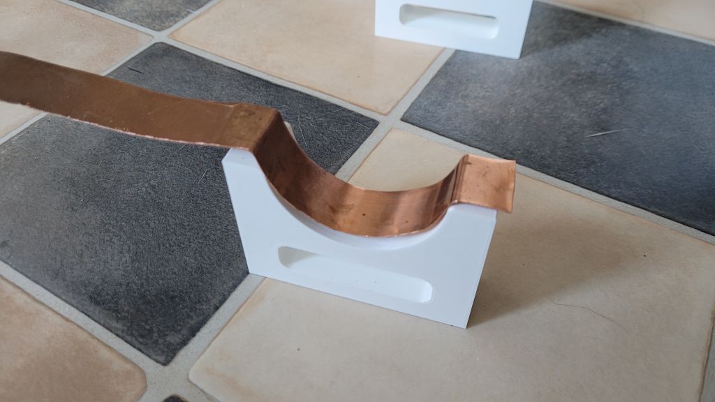
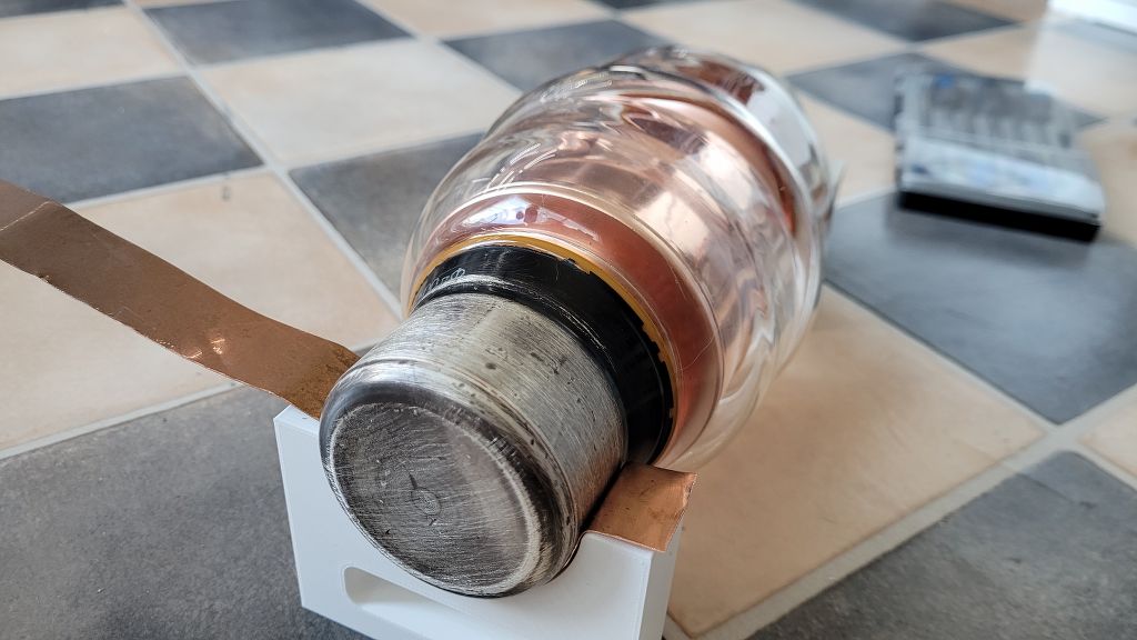
First I had to find a way to mount the vacuum condenser on the mounting plate.
Because I print a lot in 3D, I had the choice to design and print mounting brackets.
Also important to include in the design was the placement of the copper strips that run to each end of the Loop.
I was able to process this perfectly in the brackets as can be seen in the following photos.
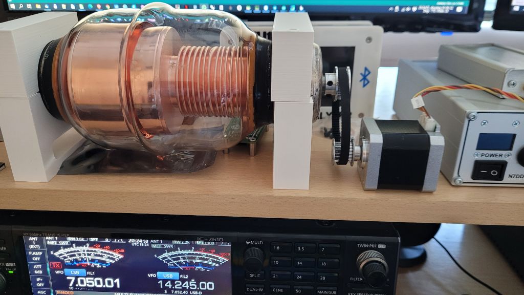
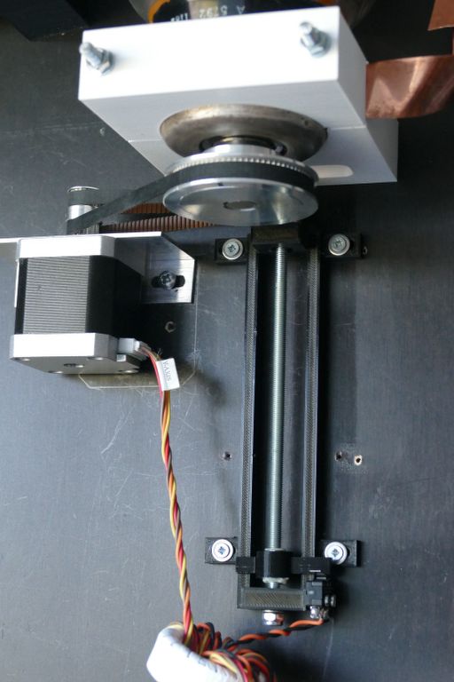
Stepper motor, and End-stop detection
The next step is to mount a stepper motor, and not unimportant is an endstop detection mechanism.
The capacitor itself needs 34 turns for the entire tuning range.
In terms of transmission, I had to take into account the force needed to rotate the capacitor’s shaft.
A 1:1 ratio was far too small, and too heavy for a NEMA 17 stepper motor.
I have opted for a 4:1 ratio here. 20 teeth pulley for Stepper motor, and 80 teeth pulley for the Vacuum condenser.
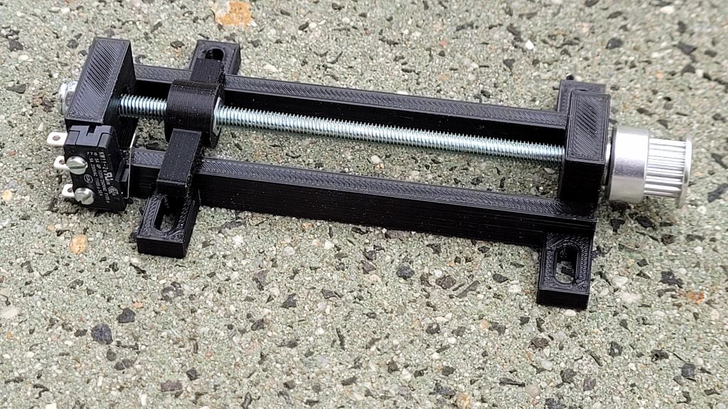
This made endstop detection in a sense a bit more difficult than a traditional air condenser, which only needs half a turn for a whole range.
To solve this I made a spindle system with simple metric M5 threaded rod.
The transmission goes directly to the stepper motor with also a 20 tooth pulley.
The ratio to the stepper motor is therefore 1:1
I use a NEMA 17 stepper motor. this one has 1.8 degrees per step.
So 200 steps for one full revolution.
With a 4:1 ratio the capacitor would need 4x 200 steps.
So 800 steps are needed for 1 revolution on the capacitor.
To make 34 complete revolutions on the capacitor, it takes: 34 x 800 = 27200 steps.
I guess I have two questions. 1. why did you use just one end stop. I ask this because your stepper motor really powerful it can easily destroy your capicator….. 2. If you put the end stop switch on the motor side wont that blow the driver IC? When you disconnect the motor there is no place for the current to go except to blow the driver IC.
Hi Tom, thanks for your response and good observation.
In the meantime the project has died down a bit.
But in the meantime the Linear endstop was also provided with 2 endstops. Exactly for protection what you mean.
It was fun to experiment with it, but because it is not a very practical system I switched back to a more simplistic system.. the dipole 🙂
73 Bjorn PD5DJ
Fantastic Job! Doing something very similar with a vacuum capacitor at the moment building a balanced L matching unit.
I’m wondering if you would consider sharing the STL for your linear end stop?
Keep up the home brew projects
Hi Jordan, My apologies for the late reply.
Yes I can supply you with the STL files for the endstop no problem.
I will arrange it in the upcoming days, Maybe I will add a section to my website specially dedicated to “requested downloads”.
73 Bjorn PD5DJ